Contents: Arrangement of elements ⇩ Arrangement of elements ⇩ Review ⇩ Description - model SVX (60th…⇩ Control scheme ⇩ Control scheme ⇩
Arrangement of elements
Models from 2007 model year onwards (except SVX model) (60th anniversary)
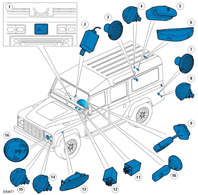
| Pos. | Spare No | Name |
| 1 | parts | Hazard warning light button |
| 2 | - | Fog light control unit |
| 3 | - | Rear fog light |
| 4 | - | Tail light/brake light |
| 5 | - | License plate light |
| 6 | - | High-mounted brake light |
| 7 | - | Reversing light |
| 8 | - | Rear direction indicator |
| 9 | - | Multi-function steering column switch |
| 10 | - | Light switch |
| 11 | - | Headlight relay |
| 12 | - | Hazard warning light relay |
| 13 | - | Side direction indicator |
| 14 | - | Front direction indicator |
| 15 | - | Side lights |
| 16 | - | Headlight(s) |
Arrangement of elements
Model SVX (60th anniversary)
NOTE: Model 90 shown, same for model 110.
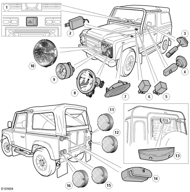
| Pos. | Spare part number | Name |
| 1 | - | Hazard warning light switch. |
| 2 | - | Fog Light Control Module |
| 3 | - | Multi-function steering column switch |
| 4 | - | Light switch |
| 5 | - | Headlight relay |
| 6 | - | Hazard warning light relay |
| 7 | - | Side direction indicator (2 pcs.) |
| 8 | - | Additional high beam headlight (2 pcs.) |
| 9 | - | Front direction indicator (2 pcs.) |
| 10 | - | Headlight with integrated side light |
| 11 | - | Tail light/brake light (2 pcs.) |
| 12 | - | Rear fog light or reversing light (depending on the market) |
| 13 | - | High-mounted brake light (except model 90) |
| 14 | - | License plate light |
| 15 | - | Rear fog light or reversing light (depending on the market) |
| 16 | - | Rear direction indicator (2 pcs.) |
Review
The operation of the exterior lighting devices is controlled by the lighting switch and the multi-function switch located on the steering column. The lighting control switch is a 3-position switch mounted on the (left) side of the steering column. When the switch is moved forward to the first position, the power is turned on (from the battery) parking lights, tail lights and license plate lights regardless of the ignition switch position. Moving the light switch forward to the second position also supplies power to the headlight relay.
The multifunction steering column switch is located in front of the light switch on the left side of the steering column; it allows the driver to switch the headlights between high beam, low beam and headlight warning. The steering column multifunction switch is powered by the headlight relay, which is activated when the ignition switch is turned to position II.
4-position rotary headlight leveling switch (with this system in place) is mounted on the dashboard and allows the driver to raise or lower the headlight beam depending on the vehicle's load. An electric motor mounted behind each headlight adjusts its position in accordance with the movement of the switch.
The multifunction steering column switch also operates the turn signals. The multifunction steering column switch is supplied with power from the ignition switch via the hazard warning relay. When the switch is moved to the left or right turn signal position, its contacts close and power is supplied to the corresponding lights. In addition, power is supplied to the instrument cluster to turn on the turn signal indicator lamp.
The hazard warning light button is located on the instrument panel; pressing it turns on/off the (left) and right () turn signals simultaneously. The hazard warning light button is supplied with power from the battery at all times, allowing it to be used regardless of the ignition switch position. When pressed, the hazard warning light button supplies power to the instrument panel, where the hazard warning light is turned on.
The brake lights are controlled by a brake light switch mounted on the top of the brake pedal. When the brake pedal is pressed, the switch contacts close and power is supplied to the brake lights from the ignition switch.
The reversing light is switched on by the reverse gear switch, which is mounted on the gearbox. When the reverse gear is engaged, the switch contacts close, and the ignition power is supplied to the reversing light.
The fog lamp operation is controlled by the fog lamp control unit, located under the right-hand (RH) front seat. The control unit receives ignition power from the switched-on headlamp relay via the central fuse block (CJB). The control unit monitors the state of the fog lamp switch. When the switch is pressed, its contacts close and a ground loop is created. Having detected a ground loop, the control unit supplies power to the rear fog lamp and to the instrument cluster.
Model SVX (60th Anniversary)
The exterior lighting system on the 2008 SVX is the same as described above, except for the following differences:
- LED tail lights
- halogen headlights with a reflector with a complex surface shape and a built-in side light
- separate high beam headlights that work while driving
- new front direction indicators.
Description - model SVX (60th anniversary)
Headlight
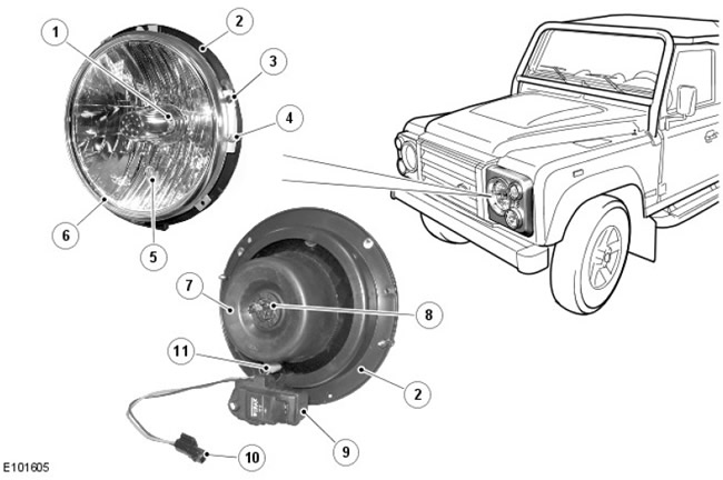
| Pos. | Spare part number | Name |
| 1 | - | Halogen lamp |
| 2 | - | Headlight support |
| 3 | - | Headlight mounting screw |
| 4 | - | Headlight adjustment screw |
| 5 | - | Side light bulb |
| 6 | - | Headlight assembly |
| 7 | - | Rubber cap |
| 8 | - | Headlight bulb connections |
| 9 | - | Headlight adjustment motor (if available) |
| 10 | - | Side light connector |
| 11 | - | Side light bulb socket |
The headlight is a unique unit to the SVX. The headlight is a Wipac unit with a reflector divided into parabolic segments, each with a different focal length. The headlight uses a halogen H4 60/55W bulb, which is held in place at the rear of the headlight with a wire clip. The headlight housing also houses the parking light, which is housed in a hole in the headlight lens. The parking light uses a W5W bayonet-type bulb, which is housed in a rubber socket. The electrical connector from the parking light mates with the existing parking light electrical connector in the main wiring harness.
The (right) headlight assembly connects to the main wiring harness. The (left) headlight connects to the main wiring harness via a jumper harness, which also supplies power to the auxiliary running lights.
An electric motor mounted on the rear of the headlight allows you to adjust the position of the headlight (with the appropriate headlight).
The headlight is attached to a metal support plate using four self-tapping screws, which is attached to the wing.
Additional high beam headlight
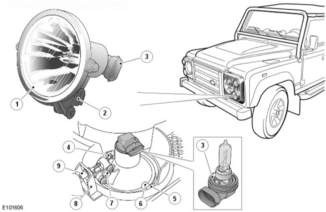
| Pos. | Spare part number | Name |
| 1 | - | Additional high beam headlight assembly |
| 2 | - | Adjustment lever |
| 3 | - | Electrical connector and halogen lamp socket |
| 4 | - | R-clamp |
| 5 | - | Hinge plate (2 pcs.) |
| 6 | - | Axle (2 pcs.) |
| 7 | - | Articulated arm |
| 8 | - | Headlight frame |
| 9 | - | Position adjustment screw |
The auxiliary high beam headlamp is a unique unit to the SVX. This headlamp is housed in the headlamp bezel. Two metal plates are press-fitted into the bezel and two pins on the headlamp fit into the plates, allowing the headlamp assembly to move up and down. This allows the headlamp to be adjusted vertically using a worm gear mechanism located on the headlamp. The adjusting screw fits into a hole in a molded tab on the headlamp bezel. The screw has a washer on each side of the tab that is secured with a snap ring. The two washers and the snap ring hold the screw in the tab, allowing the screw to rotate and set the linear movement of the headlamp, thus adjusting its position. The screw is accessed through a hole on the underside of the headlamp bezel.
The additional high beam headlight uses a 65W H9 halogen bulb, which is housed in an integral socket. The socket must be turned to lock or removed from the rear of the headlight. To access the bulb, the headlight frame must be removed.
Additional high beam headlight relay and fuse
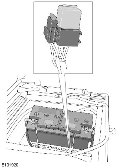
The auxiliary lights are connected via the headlamp jumper harness. Power to the left high beam headlamp is supplied via the jumper harness by activating a dedicated auxiliary high beam relay located in the battery junction box (BJB) located next to the battery. The auxiliary light circuit is protected by a 15A fuse located on the side of the relay. Activation of the relay allows power to be supplied directly from the battery to the auxiliary lights.
Front direction indicator
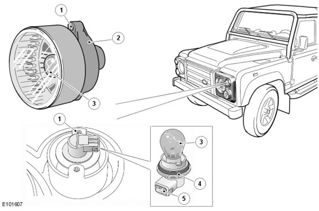
| Pos. | Spare No | Name |
| 1 | parts | Direction indicator mounting hole (2 pcs.) |
| 2 | - | Direction indicator assembly |
| 3 | - | Turn signal lamp |
| 4 | - | Lamp holder |
| 5 | - | Electrical connector |
The article was copied from this resource: lrman.ru
The front turn signal is a unique unit to the SVX. The light is located inside the headlight frame, aligned with two tabs built into the frame and secured with two self-tapping screws.
The lamp uses a PY21W Diadem bulb which is housed in a socket at the rear of the headlamp assembly. The socket has a connector built into it which allows connection to the main wiring harness using a short jumper harness which connects the main wiring harness connector to the socket on the socket. The socket must be twisted to lock or removed from the rear of the headlamp. The headlamp bezel must be removed to access the bulb.
Rear LED lights
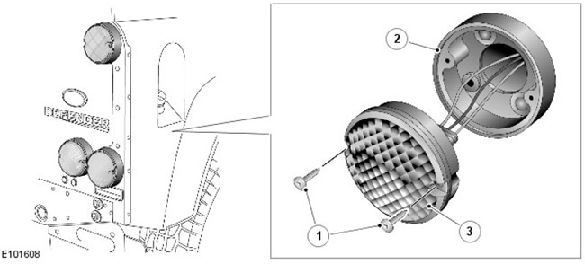
| Pos. | Spare part number | Name |
| 1 | - | Screw (2 pcs.) |
| 2 | - | Frame |
| 3 | - | (LED) lantern assembly |
(LED) the taillights are unique units to the SVX model. All lights look identical when not lit and have a white opaque lens. Once activated, (lEDs) they glow in a color corresponding to the purpose of the flashlight.
The two upper rear lights serve as rear position lights and brake lights. The inner lower lights are turn signals. On variants, the (left) outer rear light serves as a rear fog light, and the (right) outer rear light serves as a reversing light. On variant, the position of these two lights is directly opposite.
Control scheme
Models from 2007 model year onwards (except SVX model) (60th anniversary)
NOTE: A = Wired connection
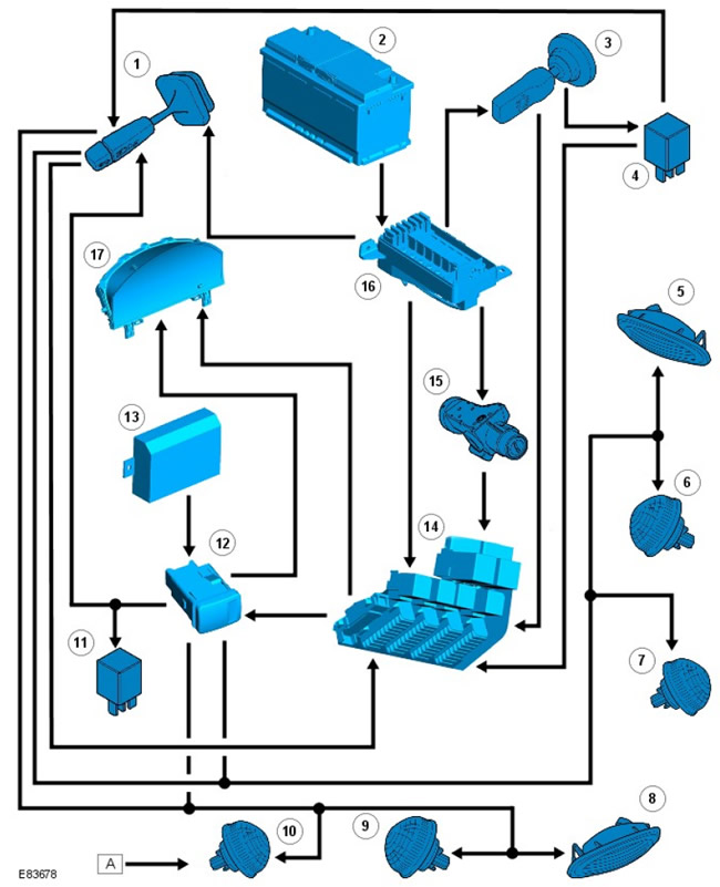
| Pos. | Spare part number | Name |
| 1 | - | Steering column switch |
| 2 | - | Battery |
| 3 | - | Turning on the lighting |
| 4 | - | Headlight relay |
| 5 | - | (Right) side turn signal |
| 6 | - | Right front turn signal |
| 7 | - | Right rear turn signal |
| 8 | - | (Left) side turn signal |
| 9 | - | Left front turn signal |
| 10 | - | Left rear turn signal |
| 11 | - | Hazard warning light relay |
| 12 | - | Hazard warning light button |
| 13 | - | Anti-theft protection system module |
| 14 | - | CJB |
| 15 | - | Ignition switch |
| 16 | - | BJB |
| 17 | - | Instrument panel |
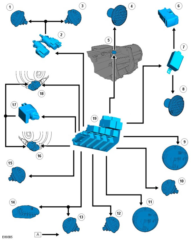
| Pos. | Spare part number | Name |
| 1 | - | Left brake light |
| 2 | - | Brake pedal switch |
| 3 | - | Right brake light |
| 4 | - | Reversing light |
| 5 | - | Reverse Light Switch |
| 6 | - | Fog light switch |
| 7 | - | Fog light control unit |
| 8 | - | Fog lights |
| 9 | - | Left headlight |
| 10 | - | Left side light |
| 11 | - | Right headlight |
| 12 | - | Right side light |
| 13 | - | Left rear light |
| 14 | - | License plate light |
| 15 | - | Right rear light |
| 16 | - | Headlamp tilt adjustment motor (right) (if any) |
| 17 | - | Headlight leveling switch (if available) |
| 18 | - | Left headlight leveling motor (if any) |
| 19 | - | CJB |
Control scheme
Model SVX (60th anniversary)
NOTE: A = Permanent wired connection
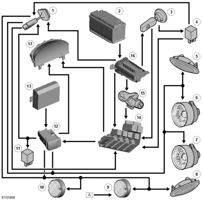
| Pos. | Spare part number | Name |
| 1 | - | Multi-function steering column switch |
| 2 | - | Battery |
| 3 | - | Light switch |
| 4 | - | Headlight relay |
| 5 | - | Side (right) turn signal |
| 6 | - | Front right turn signal |
| 7 | - | Front left turn signal |
| 8 | - | Left side turn signal |
| 9 | - | Rear right turn signal |
| 10 | - | Rear left turn signal |
| 11 | - | Hazard warning light relay |
| 12 | - | Hazard warning light switch. |
| 13 | - | Anti-theft system module |
| 14 | - | CJB |
| 15 | - | Ignition switch |
| 16 | - | BJB |
| 17 | - | Instrument panel |
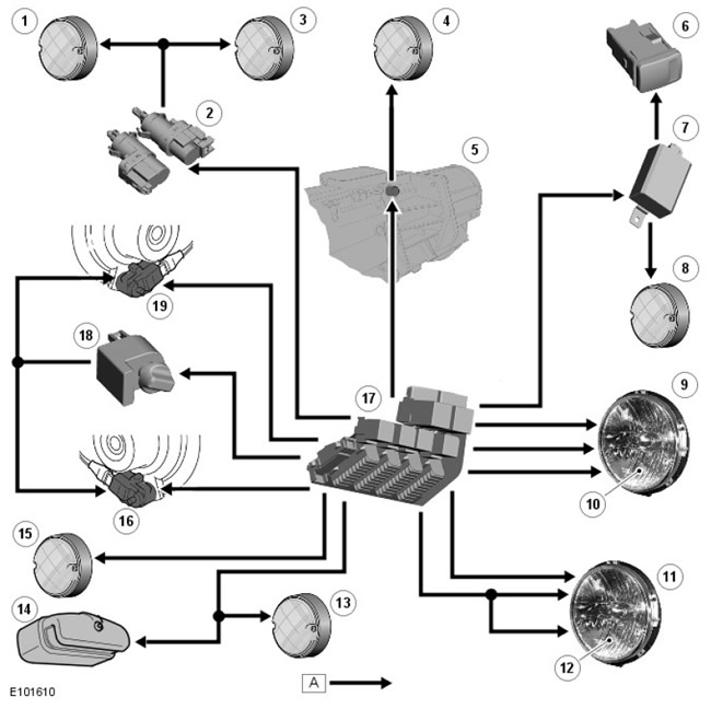
| Pos. | Spare part number | Name |
| 1 | - | Left brake light |
| 2 | - | Brake pedal switch sensor |
| 3 | - | Right brake light |
| 4 | - | Reversing light |
| 5 | - | Reverse gear indicator light switch |
| 6 | - | Fog light switch |
| 7 | - | Fog Light Control Module |
| 8 | - | Fog light |
| 9 | - | Left headlight |
| 10 | - | Left side light |
| 11 | - | Right headlight |
| 12 | - | Right side light |
| 13 | - | Left rear light |
| 14 | - | License plate light |
| 15 | - | Right rear light |
| 16 | - | Right headlight leveling motor (if any) |
| 17 | - | CJB |
| 18 | - | Headlight leveling switch (if available) |
| 19 | - | Left headlight leveling motor (if any) |
Comments on this article