Arrangement of elements
Battery Distribution Box
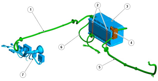
| Pos. | Spare No | Name |
| 1 | parts | Power to Battery Junction Box (BJB) |
| 2 | - | Battery terminals |
| 3 | - | Battery |
| 4 | - | Main fuse |
| 5 | - | Positive battery cable |
| 6 | - | Negative battery cable |
| 7 | - | BJB |
Review
The battery is installed in a protected box under the left seat. The battery rests on a platform to which it is attached with clamping strips and bolts.
The article is based on data from the website (LRman.ru)
The cables are attached to the battery terminals using clamp terminals.
The "positive" pole tip contains a 500 A fuse link. The link is housed in a black housing and is integral with the terminal. Power is supplied to the BJB before the main fuse, from a tap on the terminal.
The main fuse should blow in the event of a collision (if the cable is directly shorted to ground), cutting off power to the alternator and starter but maintaining power to the rest of the on-board systems via the central fuse box (CJB).
The battery type is H8 with a semi-hermetic case. Each can has a ventilation hole, which is necessary to compensate for the thermal expansion of the electrolyte and the release of oxygen and hydrogen, which are formed under certain operating conditions of the battery.
Before removing the battery, make sure the car alarm is off and the ignition is off. Always disconnect the negative terminal first, then the positive. When installing the battery, always connect the positive terminal first, then the negative.
If the battery requires recharging, always use a constant current charger designed for lead-calcium batteries. DO NOT use a quick charger as this may cause permanent damage to the battery.
Starter fuse
The 500A main fuse is built into the wire between the battery and the starter/generator. The fuse is mounted next to the positive battery terminal and is integrated with the wire assembly. If the fuse blows, the entire wire assembly must be replaced.
Central fuse box
NOTE: Left hand drive vehicle shown.
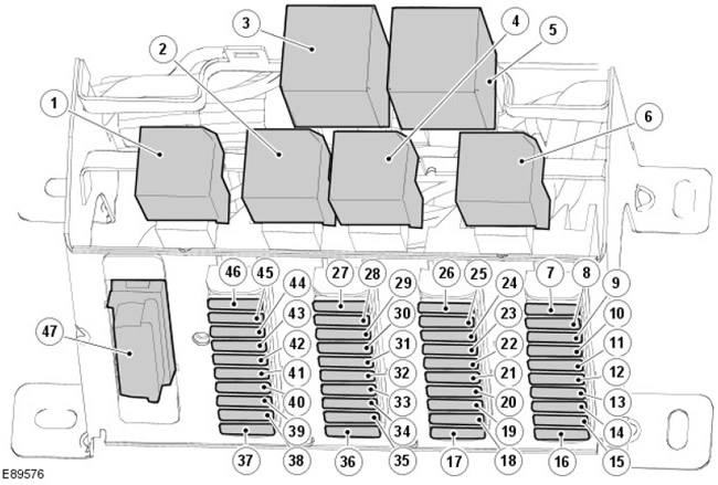
Description of CJB relay
| Location | Description |
| 1 | Headlight relay |
| 2 | Rear window heating relay |
| 3 | Wiper relay |
| 4 | Electric window relay |
| 5 | Direction indicator relay |
| 6 | Alarm relay |
CJB fuse description
| Name | Element number | Nominal (A) | Fuse color | Protected electrical circuits |
| F8 | 16 | 10 | Red | Anti-theft alarm system |
| F9 | 15 | 15 | Blue | Windshield wipers/washers |
| F10 | 14 | 10 | Red | Rear window wiper/washer |
| F11 | 13 | 10 | Red | Anti-lock braking system |
| F12 | 12 | 10 | Red | Speed sensor |
| F13 | 11 | 10 | Red | Brake lights |
| F14 | 10 | 10 | Red | Reversing light bulbs |
| F15 | 9 | 5 | Beige | Ignition |
| F16 | 8 | - | - | Not used |
| F17 | 7 | - | - | Not used |
| F18 | 17 | 10 | Red | Side lights (left) |
| F19 | 18 | 10 | Red | Side lights (right) |
| F20 | 19 | 10 | Red | Backlight/Watch Light |
| F21 | 20 | 10 | Red | Hazard warning light switch |
| F22 | 21 | 10 | Red | Low beam (right headlight) |
| F23 | 22 | 10 | Red | Low beam (left headlight) |
| F24 | 23 | 10 | Red | High beam (right headlight) |
| F25 | 24 | 10 | Red | High beam (left headlight) |
| F26 | 25 | 10 | Red | Rear fog lights |
| F27 | 26 | 10 | Red | Alarm siren |
| F28 | 36 | 20 | Yellow | Rear window heating |
| F29 | 35 | 20 | Yellow | Cooling Fan/A/C Clutch Jumper |
| F30 | 34 | 10 | Red | Audio system/clock/diagnostic connector |
| F31 | 33 | 15 | Blue | Hazard warning light switch |
| F32 | 32 | - | - | Not used |
| F33 | 31 | 20 | Yellow | Seat heater |
| F34 | 30 | 20 | Yellow | Electric window (right) |
| F35 | 29 | 20 | Yellow | Electric window (left) |
| F36 | 28 | 30 | Green | Heated windshield |
| F37 | 27 | 30 | Green | Spare fuse |
| F38 | 37 | 10 | Red | Engine ECU/PCM |
| F39 | 38 | 5 | Beige | Engine ECU/PCM |
| F40 | 39 | - | - | Not used |
| F41 | 40 | 5 | Beige | Engine ECU/PCM |
| F42 | 41 | 10 | Red | Air conditioning switch |
| F43 | 42 | 20 | Yellow | Cigarette lighter |
| F44 | 43 | 5 | Beige | Audio system |
| F45 | 44 | 30 | Green | Electric blower fan |
| F46 | 45 | - | - | Not used |
| F47 | 46 | - | - | Not used |
| Diagnostic connector | 47 | - | - | Diagnostic connector |
The central fuse box is located on the side under the steering column. To access the fuses, turn the mounting screws fully counterclockwise and remove the cover.
NOTE: Some early 07MY models have CJBs that differ in the side they are installed on. The illustration above shows the left hand (LH) version fitted to all other vehicles. The early right hand (RH) version is a mirror image of the standard LH left hand CJB.
Battery Distribution Box
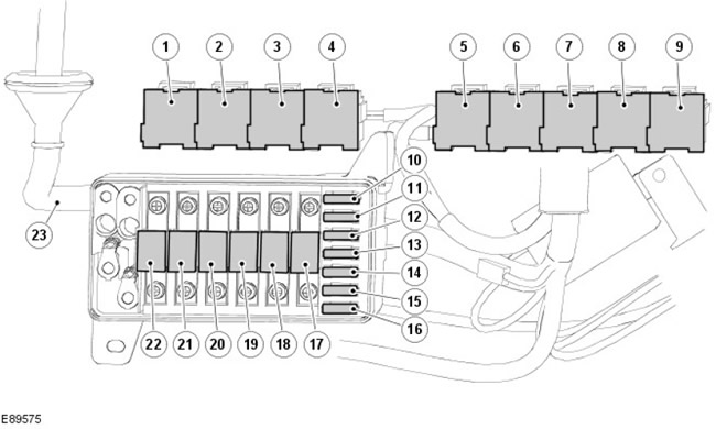
Description of the relay (VDO)
| Element number | Description |
| 1 | Anti-lock Brake System (ABS) Pump Relay |
| 2 | Power relay |
| 3 | Starter relay |
| 4 | Glow Plug Relay |
| 5 | Air conditioning clutch relay |
| 6 | Air Conditioning Cooling Fan Relay |
| 7 | Air conditioning auxiliary equipment relay |
| 8 | Windshield heating relay |
| 9 | Glass heating timer relay |
Description of VDO fuses
| Name | Element number | Nominal (A) | Fuse color | Protected electrical circuits |
| F1 | 16 | 30 | Green | Anti-lock braking system |
| F2 | 15 | 20 | Yellow | Socket for connecting additional equipment |
| F3 | 14 | 20 | Yellow | High beam headlights/horn alarm |
| F4 | 13 | 20 | Yellow | Not used |
| F5 | 12 | 30 | Green | Main Relay/Engine Control Module (ECM) |
| F6 | 11 | 15 | Blue | Anti-theft alarm system |
| F7 | 10 | 20 | Yellow | Anti-theft alarm system |
Description of VDO fuse links
| Element number | Nominal (A) | Fuse color | Protected electrical circuits |
| 22 | 100 | Blue | Glow Plug Relay, Fuses 2, 3 and 4, Fuses 1, 2 and 3 and Fuse 36 in CJB |
| 21 | 60 | Yellow | CJB Battery Power |
| 20 | 60 | Yellow | Window lifter relay |
| 19 | 30 | Green | ABS return pump |
| 18 | 60 | Yellow | Ignition Switch/Starter Relay |
| 17 | 30 | Green | Light switch |
| 23 | - | - | Main power supply from battery |
The battery junction box is located under the right front seat and can be accessed by removing the seat base.
Comments on this article