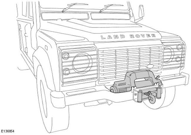
Location of components
Control Chart
NOTE: A = wired connection
Connection to the car
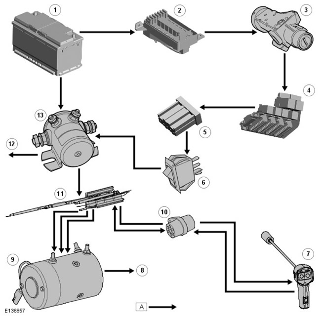
| Pos. | Name |
| 1 | Accumulator battery |
| 2 | Battery Junction Box (BJB) |
| 3 | ignition switch |
| 4 | Passenger side fuse box |
| 5 | Harness connector C0072-1: Heated rear window switch (for reference only) |
| 6 | Winch Power Interrupt Solenoid Switch |
| 7 | Remote control |
| 8 | grounding |
| 9 | winch motor |
| 10 | Remote control socket |
| 11 | Control block |
| 12 | Grounding the winch power interruption solenoid |
| 13 | Winch power interruption solenoid |
Schematic diagram of the electrical circuit of the winch
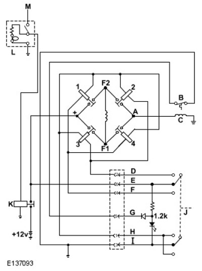
| Pos. | Name |
| A | Field |
| B | Thermal switch: normally closed |
| C | Anchor |
| D | white wire |
| E | red wire |
| F | Green wire |
| G | blue wire |
| H | brown wire |
| I | black wire |
| J | Remote control (power up/down) |
| K | Winch power interruption solenoid |
| L | Winch Power Interrupt Solenoid Switch (mounted on the instrument panel) |
| M | 12V power supply from heated rear window switch ignition circuit |
Electrical connections for winch motor/control box
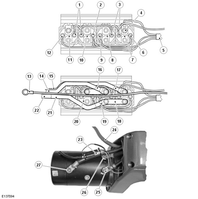
| Pos. | Name |
| 1 | brown wire |
| 2 | Green wire |
| 3 | Brown wire from socket |
| 4 | Red wire from connector |
| 5 | Remote Control Wiring Harness |
| 6 | Green wire |
| 7 | Electromagnet #1 |
| 8 | Electromagnet #2 |
| 9 | white wire |
| 10 | Electromagnet #3 |
| 11 | Electromagnet #4 |
| 12 | white wire |
| 13 | Control panel grounding |
| 14 | Armored cable «A» (to winch motor) |
| 15 | Positive (+) cable (to power interruption solenoid) |
| 16 | Armored cable lug «A» |
| 17 | Positive (+) battery cable terminal |
| 18 | Tire (3 in each node) |
| 19 | Field cable lug «F2» |
| 20 | Field cable lug «F1» |
| 21 | Field cable «2» (to winch motor) |
| 22 | Field cable «1» (to winch motor) |
| 23 | Thermal switch connector |
| 24 | Positive (+) cable (to power interruption solenoid) |
| 25 | Field cable connection «F2» |
| 26 | Field cable connection «F1» |
| 27 | Armored cable connection «A» |
Operating principle
WARNING: When preparing and operating the winch, follow all warnings and cautions given in the WARN winch user manual and the WARN winch summary.
The winch motor is powered by the car battery. The electric motor transmits torque to the gear train, which, in turn, rotates the winch drum and provides cable winding.
The remote control is used to control the winch. The remote control wire plugs into the remote control connector connected to the control box, allowing the user to control the winding direction from a safe distance from the winch cable.
Remote control equipped with LED (Light-emitting diode) an indicator that lights up when the motor reaches the maximum allowable temperature. The electric motor does not turn off. The user must wait until the winch has cooled down and continue working only when the indicator goes off.
The clutch allows you to unwind the cable from the drum without turning on the electric motor. See a summary of WARN winch methods.
Description
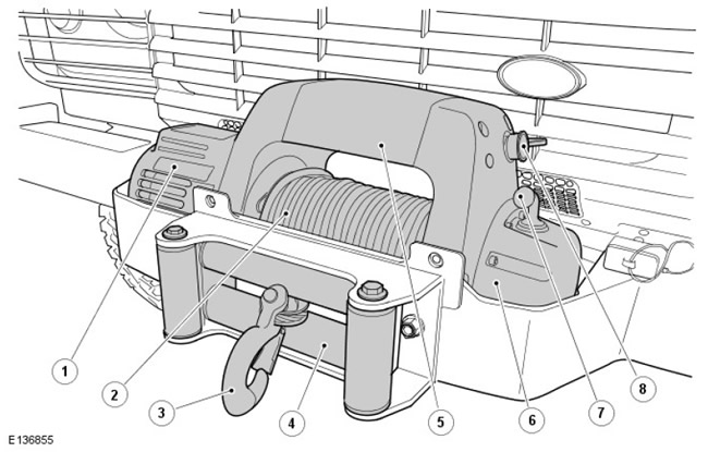
| Pos. | Name |
| 1 | electric motor; |
| 2 | Winch drum and wire rope |
| 3 | snap hook |
| 4 | Rope handler |
| 5 | Control block (is hidden) |
| 6 | Gear housing |
| 7 | clutch lever |
| 8 | Remote control socket |
The winch must be installed on the front bumper. The winch is attached to the bracket with four bolts, washers and nuts.
The winch control unit is built into the winch housing above the winding drum.
The winch control unit regulates the power supply to the electric motor, and also receives a control signal from the remote control. The remote control socket is on the LH (left) side of the winch housing and allows you to connect a remote control.
The winch will operate when the ignition is on, the winch power interruption solenoid switch is in the «On» (On) and the engine off, but this mode of operation is not recommended due to excessive discharge of the battery. It is recommended to turn on the engine every time the winch is used.
Winch/Vehicle Electrical Connections
The blue wire goes into the C0072-1 harness connector which is the heated rear window switch connector. The blue wire is connected to the winch power interrupt solenoid switch located on the outer center of the instrument panel. The white switch wire runs from the instrument panel to the battery compartment where it connects to the winch power interruption solenoid. This connection supplies power from the ignition circuit to the winch power cut solenoid relay when the ignition is on and the winch power cut solenoid switch is in the «On» (On).
The red cable is fixed on the positive (+) battery terminal and the positive terminal of the electromagnet. This connection supplies power to the motor and control unit via the winch power interruption solenoid. The winch power cut solenoid is located in the battery compartment under the front LH seat. The heavy gauge red wire from the winch power cut solenoid is routed to the winch control box. No power is supplied to the winch control box until the winch power interrupt solenoid switch on the instrument panel is turned to «On» (On), which is confirmed by turning on the backlight of the switch.
Winch power interruption solenoid
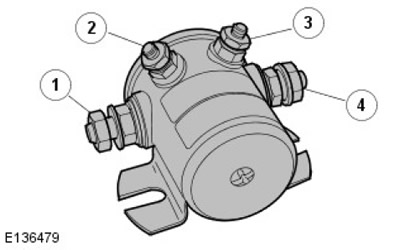
| Pos. | Name |
| 1 | Power winch motor |
| 2 | grounding |
| 3 | Electromagnet power (with the ignition on) |
| 4 | Powered by positive (+) battery terminals |
Exploded view of a winch
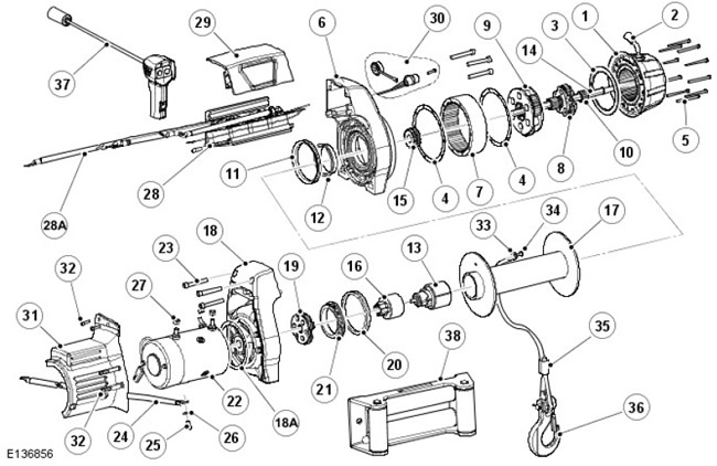
| Pos. | Name |
| 1 | End cap assembly |
| 2 | clutch lever |
| 3 | Nylon thrust washer |
| 4 | Housing gasket |
| 5 | End screw (10 pieces.) |
| 6 | Gear drum |
| 7 | ring gear |
| 8 | Planet carrier assembly (stage 2) |
| 9 | Planet carrier assembly (stage 3) |
| 10 | sun gear |
| 11 | V-shaped O-ring seal |
| 12 | drum sleeve |
| 13 | Brake assembly |
| 14 | Barbell |
| 15 | drive shaft spline |
| 16 | Motor connector |
| 17 | Drum assembly |
| 18 | Motor support drum |
| 18A | Electric motor gasket |
| 19 | Planet carrier assembly (stage 1) |
| 20 | V-shaped O-ring seal |
| 21 | drum sleeve |
| 22 | electric motor; |
| 23 | End screw (6 pcs.) |
| 24 | Electrical cable (black) |
| 25 | Hex socket head screw |
| 26 | Washer |
| 27 | screw |
| 28 | Control unit 9.5Ti assembly |
| 28A | Electrical cable (red) |
| 29 | control box cover |
| 30 | Remote control socket |
| 31 | motor cover |
| 32 | End screw (4 things.) |
| 33 | clamp kit |
| 34 | socket screw with round head |
| 35 | wire rope |
| 36 | snap hook |
| 37 | Remote control |
| 38 | Stacker roller |
| 39 | Seal kit |
Comments on this article