NOTE: An exhaust system without DPF is also available on vehicles from model year 2008.
The DPF system reduces diesel particulate emissions to negligible levels.
Elements of the DPF system
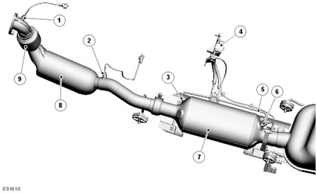
| Item name | Spare part number | Description |
| 1 | Exhaust temperature sensor (before the catalyst) | |
| 2 | Exhaust temperature sensor (after catalyst) | |
| 3 | high pressure sensor tube | |
| 4 | Differential pressure sensor | |
| 5 | Low pressure sensor tube | |
| 6 | Exhaust temperature sensor (after DPF) | |
| 7 | particulate filter | |
| 8 | catalytic converter |
Particulate matter is emitted as black smoke from a diesel engine under certain load conditions. Exhaust gases are a complex mixture of solid and liquid elements, the particulate matter being mainly microspheres of carbon on which hydrocarbons released from fuel and engine lubricants condense.
The DPF system consists of the following elements:
- particulate filter
- DPF control software built into the engine control module (ECM)
- Differential pressure sensor
Particulate filter
The DPF is located in the exhaust system, behind the catalytic converter. The main characteristic of the DPF is its ability to regenerate. Regeneration is the combustion of solid particles trapped in the filter, which prevents blockage of the filter and allows the free passage of exhaust gases. The regeneration process occurs at calculated intervals and is not noticeable to the driver of the car.
Regeneration plays a very important role, since an overfilled filter can cause engine damage due to excessively high exhaust back pressure, and the filter itself can break or be destroyed. The products captured by the filter are mainly carbon particles with adsorbed hydrocarbons.
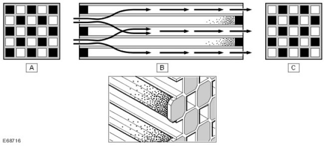
| Item name | Spare part number | Description |
| A | Front side with alternating closed cells | |
| B | Side view showing the exhaust gas flow through the filter and the particulate matter collected in the filter | |
| C | Back side with alternating closed cells |
DPF uses filtration technology based on a catalytic coated filter. The DPF is made of silicon carbide encased in a steel container, which has excellent thermal shock resistance and thermal conductivity characteristics. The DPF is designed with operational needs in mind to maintain optimum back pressure.
The porous surface of the filter consists of many small parallel channels located longitudinally with respect to the exhaust system. Adjacent channels in the filter are alternately closed at the end. This design forces the exhaust gas to pass through the porous filter walls, which act as a filter medium. Solids too large to pass through the porous surface are collected and stored in the channels.
If the solids that collect on the filter are not removed, the passage of exhaust gases may be obstructed. To remove solid particles, a regeneration process is used, in which the solid particles are oxidized.
The regeneration of the DPF is controlled by the exhaust gas temperature and the DPF. The DPF has a filter surface treated "wash coat", which includes platinum and other active components and is similar to the processing of a catalytic converter. At certain exhaust gas and DPF temperatures "wash coat" activates the combustion of particulate matter in addition to the oxidation of carbon monoxide and hydrocarbons.
Exhaust gas and DPF temperatures are controlled by the DPF software in the ECM. The DPF software monitors DPF load based on driving style, distance traveled, and signals from differential pressure sensors and temperature sensors. When the predetermined level of solids volume is reached, the DPF is actively regenerated. It is carried out in cooperation with the ECM through the regulation of various engine management functions, such as:
- fuel injection
- intake air flow control with throttle
- exhaust gas recirculation system
- boost pressure control
Two filters are used for DPF regeneration - active and passive.
Passive regeneration
Passive regeneration does not require special intervention from the engine management system and occurs during normal engine operation. Due to passive regeneration, solid particles deposited in the DPF are slowly converted into carbon dioxide. This process is active when the DPF temperature reaches 250°C (482°F). At high speeds and heavy load on the engine, this process becomes continuous.
During passive regeneration, only part of the particulate matter is converted to carbon dioxide. This is because the chemical reaction process is only effective within the normal operating temperature range of 250°C to 500°C (482°F to 932°F).
Above this temperature range, the efficiency of converting particulate matter to carbon dioxide increases with increasing DPF temperature. These temperatures can only be achieved with an active regeneration process.
Active regeneration
Active regeneration begins when the amount of particulate matter in the DPF reaches a threshold level that is monitored or determined by the DPF control software. The threshold calculation takes into account driving style, distance traveled and backpressure signals from the differential pressure sensor.
As a rule, active regeneration occurs every 725 km, but the frequency of regeneration is highly dependent on the driving conditions of the car. For example, when driving a car with a small load in city traffic, active regeneration will occur more often. This is caused by a faster accumulation of particulate matter in the DPF compared to modes where the vehicle is driven at high speed and passive regeneration occurs.
The DPF software contains an odometer that initiates the regeneration and serves to back up the active regeneration. Regeneration is requested based on distance travelled, unless initiated by a backpressure signal from a differential pressure transmitter.
Active DPF regeneration starts when the DPF temperature rises to the particulate combustion temperature. The DPF temperature is increased by increasing the exhaust gas temperature. This is achieved by introducing an additional injection after the pilot and main injection.
The DPF software monitors the signals from the two DPF temperature sensors to determine the DPF temperature. Depending on the DPF temperature, the DPF software will request the ECM to perform one or two post-fuel injection cycles:
- The first after-injection of fuel slows down the combustion inside the cylinder, which increases the exhaust gas temperature.
- The second post-fuel injection occurs later in the power stroke cycle. The fuel partially burns in the cylinder; some of the unburned fuel enters the exhaust system, where it initiates an exothermic reaction in the catalytic converter, further increasing the temperature of the DPF.
The active regeneration temperature of the DPF is carefully controlled by the DPF software to maintain the required temperature of 600°C (1112°F) at the DPF inlet. The temperature control system prevents the turbocharger and catalytic converter from exceeding operating temperature limits. Turbocharger inlet temperature must not exceed 830°C (1526TF), the temperature of the catalytic converter must not exceed 800°C (1472TF), and the outlet temperature must remain below 750°C (1382°F).
During active regeneration, the following processes take place, controlled by the ECM:
- The turbocharger is maintained in the fully open position. This minimizes heat transfer from the exhaust gas to the turbocharger and reduces the exhaust gas flow rate to achieve optimum DPF warm-up. If the driver wishes to increase the torque, if necessary, the turbocharger vanes can be closed.
- The throttle valve closes as this helps increase the exhaust gas temperature and reduces the exhaust gas flow rate, which shortens the time for the DPF to warm up to the optimum temperature.
- The exhaust gas recirculation valve closes (EGR). The use of EGR reduces the exhaust gas temperature and therefore does not achieve the optimum DPF temperature.
Diesel particulate filter control system
To achieve optimal DPF performance and prevent clogging, the condition of the DPF must be constantly monitored. The ECM contains DPF software that manages the monitoring and operation of the DPF system and also monitors other vehicle data to determine regeneration periods and service intervals.
The DPF software can be divided into three separate control software modules: the DPF control module, the DPF fuel flow control module, and the DPF air flow control module.
These three modules are controlled by a fourth software module, which is called the DPF matching module. The matching module controls the operation of other modules when an active regeneration is requested. The DPF control module is a subsystem of the DPF matching module.
DPF Fuel Control Module
The DPF fuel management module controls the following functions:
- Synchronization of four separate injections per working stroke and the amount of fuel injected (preliminary, main and two additional injections).
- Injection pressure and switching between three different levels of injection calibration.
In addition to measuring catalyst activity and DPF, controlled injection determines the required injection level. The fuel management system calculates the amount of fuel and the timing of four separate injections for each of the three levels of injection pressure calibration, and controls the switching between levels.
Two additional injections are required to separate the functions of increasing the temperature of the gases in the cylinder and producing hydrocarbons. The first post-injection is used to generate a higher temperature of the gases in the cylinders at the same time as maintaining the same engine torque as in normal (not during regeneration) engine operation. The second post-injection is used to generate hydrocarbons by directing unburned fuel to the catalytic converter without increasing engine torque.
DPF air flow control module
The DPF air flow control module controls the following functions:
- EGR control system
- boost pressure control system
- Intake air temperature and pressure control system
The module controls the intake air temperature by actuating the EGR throttle and adjusting the boost pressure.
DPF matching module
The DPF Coordinating Module, upon receiving a regeneration request from the control module, initiates and coordinates the following DPF regeneration requests:
- Disable EGR
- Boost pressure control
- Increased engine load
- Manifold air pressure and temperature control
- Fuel injection control
When the EGR valve closes, the coordinating module initiates a request for an increase in engine load by controlling intake air temperature and pressure.
After receiving confirmation that intake conditions are under control or that the calibration time has elapsed, the matching module goes into a state of waiting for the driver to release the accelerator pedal. If this happens or the calibration time expires, the matching module generates a request for fuel injection control to increase the exhaust gas temperature.
Differential pressure sensor
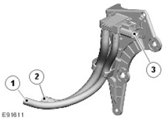
| Item name | Spare part number | Description |
| 1 | Low pressure connection | |
| 2 | High pressure connection | |
| 3 | electrical connector |
The differential pressure sensor is mounted on a bracket attached to the transfer case.
The differential pressure sensor is used by the software to monitor the status of the DPF. The two pipes on the sensor are connected by pipes to the inlet and outlet side of the DPF. The tubes allow the sensor to measure intake and exhaust DPF pressure.
As the amount of particulate matter captured by the DPF increases, the pressure on the intake side of the DPF increases compared to the exhaust side. The DPF software uses this comparison in combination with other data to calculate the accumulated number of trapped particles.
By measuring the pressure difference between the DPF inlet and outlet and the DPF temperature, the DPF software can determine if the DPF is clogged and needs to be regenerated.
DPF temperature sensors
The DPF system uses three temperature sensors. The first sensor is located immediately after the turbocharger in the catalytic converter inlet pipe, the second is located in the catalytic converter outlet pipe, and the third sensor is in the DPF outlet cone pipe.
The sensors measure the exhaust gas temperature at the outlet of the turbocharger, after the catalytic converter and after passing through the DPF and provide the information needed to calculate the DPF temperature.
This information is used in conjunction with other data to calculate accumulated particulate matter and to control DPF temperature.
Indication on the instrument panel
If the vehicle regularly makes short trips at low speed, effective DPF regeneration may not be possible.
In this case, the DPF software determines that the DPF is clogged based on signals from the differential pressure sensor and issues the following warnings to the driver:
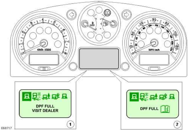
| Item name | Spare part number | Description |
| 1 | 'DPF FULL VISIT DEALER' (DPF FULL, VISIT DEALER) | |
| 2 | 'DPF FULL' (DPF FULL) |
Vehicles equipped with a DPF and a high-level instrument cluster use messages on the message center display to alert the driver of DPF status.
When the DPF fills up, the driver will be informed by a message "DPF FULL", followed by a lookup symbol. As described in the Owner's Manual, the driver must drive the vehicle until the engine has warmed up to normal operating temperature and then continue driving at a speed of at least 30 mph (48 km/h) for 20 minutes. After the successful completion of the DPF regeneration, the message "DPF FULL" will stop showing.
If the DPF software determines that the DPF is still clogged, a message will be displayed "DPF FULL VISIT DEALER". The driver should visit an authorized dealer for forced DPF regeneration.
Side effects of the particulate filter (DPF)
The following section describes some of the side effects caused by the active regeneration process.
Engine oil dilution
Dilution of the engine oil can occur due to a small amount of fuel entering the crankcase during the post-injection phase. For this reason, calculations based on driving style have been introduced to reduce oil change service intervals if necessary. The driver is notified of the need to change the oil by a message on the instrument panel.
The DPF software monitors the driving style, frequency and duration of active regeneration. With this information, calculations can be made about the dilution of the engine oil. When the DPF software calculates that engine oil dilution has reached a predetermined threshold (fuel is 7% of the volume of oil), a service message is displayed on the instrument panel.
Depending on your driving style, some vehicles may require an oil change before the scheduled interval. If a service message is displayed, the vehicle needs a full service, after which the service interval counter will be reset.
Fuel consumption
During the DPF active regeneration process, fuel consumption increases. However, since active regeneration occurs infrequently and for a limited period of time, the overall fuel consumption increases by approximately 2%. The extra fuel used during the active regeneration process is added to the instantaneous fuel consumption and the average fuel consumption is displayed on the instrument panel.
Comments on this article