car logo Ford
car logo Volkswagen
car logo BMW
car logo Opel
car logo Audi
car logo Toyota
car logo Peugeot
English Русский
Български
Беларускі
Український
Српски
Hrvatski
Română
Polski
Slovenský
Magyar


Main
Freelander
Discovery
Range Rover
Defender
Contacts
Articles

Bridge assembly — removal and installation (Defender 2007+)

 
  • Main
  • Defender
  • Defender 2007+
  • Chassis
  • Rear drive axle
  • Bridge assembly — removal and installation
 
        0  
Contents: Removal ⇩ Installation ⇩

Removal


WARNING: Removal and installation of the bridge requires two additional people to support the bridge while lowering or moving it.


1. Drain the brake fluid from the brake system.
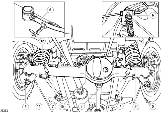
1. Drain the brake fluid from the brake system.


2. Place supports under the rear of the chassis.

3. Remove the wheels.

4. Place a hydraulic jack under the bridge.

[The original article can be found here: www.lrman.ru]

5. Disconnect the shock absorbers.

6. Release the brake hose from the clamp on the right chassis spar and disconnect the ventilation hose, disconnect the "banjo" type nipple connection (with hollow screw) on the drive axle housing.

7. Disconnect the lower arms from the axle.

8. Mark the differential and propeller shaft flanges to facilitate assembly.

9. Unscrew the 4 nuts, remove the corresponding bolts, lower the cardan shaft and tie it to the side.

10. Disconnect the ball joint of the steering bracket on the bridge bracket.

11. Loosen the bolts and remove the spring mounting strips.

12. Lower the bridge and remove the springs.

13. If applicable, remove the stabilizer bar links from the axle.

For more information, please refer to the chapter: Stabilizer Bar (204-02, Removal and installation).


14. Remove the bridge assembly.

Installation


1. Install the axle and connect the lower arms. Tighten the fasteners to 176 Nm.

2. If applicable, connect the stabilizer links to the axle.

For more information, please refer to the chapter: Stabilizer Bar (204-02, Removal and installation).

3. Raise the bridge and install the springs.

4. Install the spring mounting strips and secure them with bolts.

5. Connect the ball joint of the steering bracket to the bridge bracket. Tighten the fastening element to 176 Nm.

6. Align the propeller shaft with the differential flange and tighten the fastening elements to 47 Nm.

7. Connect the brake hose and the axle ventilation hose.

8. Install the shock absorbers.

9. Fit the wheels and tighten them to the specified torque: Alloy wheels - 130 Nm. Steel wheels - 100 Nm. Heavy-duty wheels - 170 Nm.

10. Remove the support from under the rear of the chassis.

11. Remove air from the brake system.

For more information, see the chapter: Brake System Bleeding (206-00, General Procedures).


This article is available at russian, bulgarian, belarusian, ukrainian, serbian, croatian, romanian, polish, slovak, hungarian
Article review: Saveliy Ushakov


Previous articles
Rear Drive Axle/Differential Specifications
Diagnostics and checks of the rear axle
Description and operating principle of the rear axle
Differential box 90

Current article
Bridge assembly — removal and installation

Next articles
Disassembly and assembly of the bridge 110/130
Disassembly and assembly of the bridge 90/110
Short shaft guide bearing 110/130
Short shaft guide bearing 90
Pinion Seal 110/130
Drive gear seal 90


Similar articles from Land Rover repair manuals:
• Assembled bridge Discovery 3 (2004-2009)

Comments on this article


No comments yet


How much will 25 + 41 =


Defender 2007+ 
  • General information
  • Maintenance
  • Identification codes
  • Power unit
  • Diesel engine ID4 2.4L
  • Engine inspection
  • Engine cooling
  • Fuel supply
  • Fuel tank
  • Exhaust system
  • Accessory drive
  • Air filtration
  • Electronic parts
  • Mechanical gearbox
  • Transfer case
  • Clutch
  • Chassis
  • Car suspension
  • Wheels and tires
  • Steering
  • Steering column
  • Brake system
  • Front drive axle
  • Rear drive axle
  • Cardan shaft
  • Body and coating
  • Interior trim
  • Instrument panel and console
  • Exterior finish
  • Lockable body parts
  • Handles, locks, latches
  • Glass, frames and mechanisms
  • Windshield wipers and washers
  • Seats
  • Electrical equipment
  • Battery
  • Generator and regulator
  • Lighting and headlights
  • Winch
  • Heating and ventilation
  • Instrument panel
  • Other electronics


LRman.ru © 2013-2026 | Mobile version | Free Lander | Discovery | Range Rover | Defender | Contacts | | Sitemap |
Car repair and service instructions Land Rover: Freelander, Discovery, Range Rover, Defender
We use cookies to make pages load faster and provide a more user-friendly experience 🍪