Disassembly
1.
NOTE: *This procedure is applicable to 110 and 130 models starting with the following VIN:
- 110 without ABS - 638164
- 110 Heavy Duty and 130 without ABS - 638224
- 110 Heavy Duty and 130 without ABS - 638134
Remove the differential assembly.
2. Mount the differential assembly in a vise or stand.
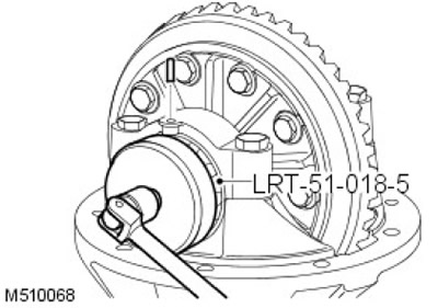
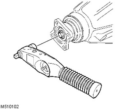
3. Knock out the adjusting nut roll pins using LRT 51-018/5 to release the adjusting nuts.
4. Mark the bearing caps for ease of assembly.
5. Turn out four bolts of fastening of covers of bearings and remove covers.
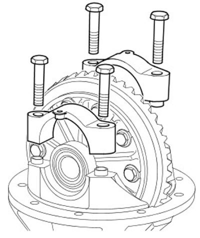
6. Remove the ring gear assembly and bearing outer races.
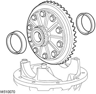
7. Mark the outer races of the bearings if the bearings are to be reused.
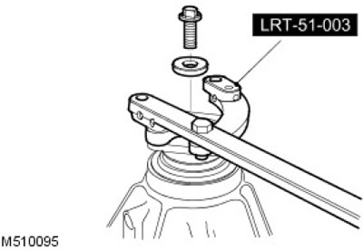
8. Using tool LRT-51-003 to hold the pinion flange, remove the bolt and washer.
9.
NOTE: Older front differentials have a square flange and an additional spacer. This spacer must be removed. Later versions of the front differential have a round flange but no spacer.
Remove the drive gear flange.
10. Using a lever, remove the gear oil seal.
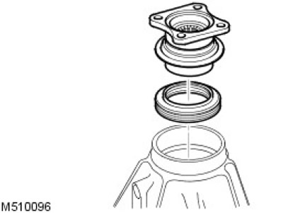
CAUTION: Be careful not to damage the oil seal groove.
11. Carefully remove the gear from the crankcase along with the rear bearing.
12. Remove the pinion rear bearing spacer and note the size of the spacer.
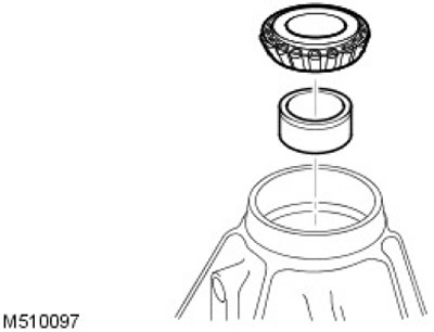
CAUTION: Do not reject the spacer at this stage.
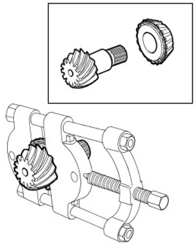
13. Using a bearing puller, remove the pinion front bearing if it needs to be replaced.
14. Remove the rings of the front and rear bearings.
15. Remove the gear front bearing shim and note the shim size.
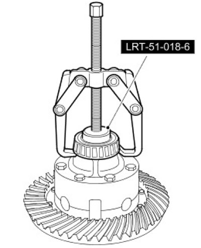
16. Using a two-arm puller and LRT 51-018/6, remove the differential bearings.
17. Secure the ring gear assembly in a vise.
18. For ease of assembly, mark the position of the ring gear relative to the holder.
19. Remove and discard the 10 ring gear-to-holder bolts.
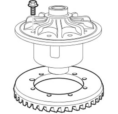
20. Carefully remove the ring gear from the holder.
21. Mark the position of the differential case for ease of assembly.
22. Turn out 8 bolts of fastening of the top section of a case of differential and remove a case.
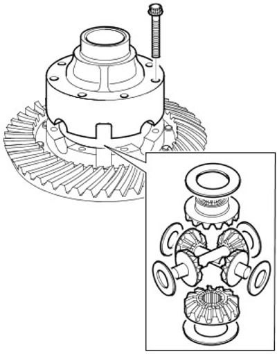
23. Remove the top sun gear and shim.
24. Noting their installation position, remove the satellites and axles. Remove the spherical washer from each satellite.
25. Remove the lower sun gear from the lower section of the differential case. Remove the adjusting shim.
26. Clean and inspect all components for wear and damage.
Assembly
1. Lubricate the sun gear, pinions, spherical washers, shims and axles.
2. Install a shim on the lower sun gear and install the sun gear on the lower section of the differential case.
3. Install all planets, axles and spherical washers in the lower section of the differential case. Make sure the gears and axles are properly fixed.
4. Place a shim on the upper sun gear and position the upper sun gear in relation to the pinion gears ensuring proper engagement.
5. With the reference marks on the differential case aligned, install the upper section of the differential case. Screw in the bolts and gradually tighten them in a cross sequence to 32 Nm.
6. Install the ring gear on the carrier, ensuring that the reference marks are aligned. Screw in new bolts and gradually tighten them to 60 Nm.
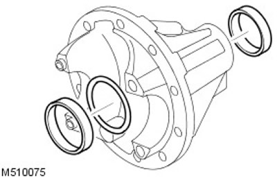
7. Clean and deburr the original pinion front bearing shim. Install the shim into the recess in the outer race of the bearing.
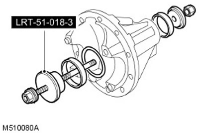
8. Using LRT 51-018/3, install the front and rear bearing outer races.
9. Apply a thin coat of oil to the bearings.
10. Install the front bearing on the drive gear.
11. Install gear into gear housing and hold in place
12. Clean original spacer and deburr. Install on the shaft - gear so that the groove in the spacer faces the drive flange. Firmly press the spacer against the pinion front bearing.
13. Install the pinion rear bearing.
14. Install drive gear flange, washer and bolt.
15. Use LRT-51-003 to hold gear flange.
16. Tighten the pinion flange bolt to 100 Nm.
17. Check the gear for end play. If the reading is zero.
18. Rotate the gear several times until the bearings are in a stable position. Check the torque of the drive gear. The turning moment should be recorded when turning the gear. The turning torque of the drive gear should be 4 - 6 Nm.
19. Adjust the size of the spacer to get the correct torque (approx. 0.025 mm = 1 Nm).
NOTE: To increase torque, install a narrower spacer.
To reduce turning torque, install a wider spacer.
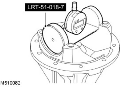
20. Install the LRT-51-018/7 tool on a flat plate, secure the DTI with a set screw, and zero the DTI reading.
21. Check that the gear height adjustment block, indicator, and mating surfaces are clean and free of any burrs.
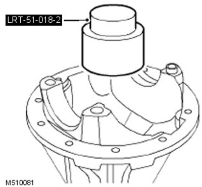
22. Install the adjusting block LRT - 51018/2 on the gear head, correctly positioning it in the required position.
23. Gear height adjustment procedure: C = 'A' - 'B'. Subtract nominal gear height 'A' from adjuster block height 'B' (on the side of the control block). Example: 76.04 - 74.7 = 1.34 mm. Therefore, the gear head height reading is 1.34 mm±0.025 mm.
- 1. 'A' = Nominal gear height, 76.04.
- 2. 'B' = Adjustment block height.
- 3. 'C' = Head height.
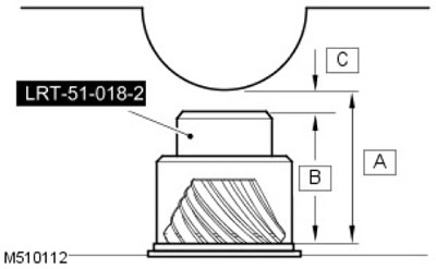
CAUTION: The height of the adjusting block should be checked against the numbers printed on the side of the block.
24. Install the LRT indicator -51-018-7 on the adjusting block and shake it to get the minimum reading. If the reading is lower than required, reduce the shim size. If the reading is higher than required, increase the shim size.
25. Using tool LRT-51-003 to hold the pinion flange, remove the bolt and washer. Remove the drive gear flange.
26. Remove pinion gear, rear bearing and rear bearing spacer.
27. Remove the outer race and the front gear bearing shim. Discard the adjusting shim. Clean the recess in the bearing ring and deburr it.
28. Install a shim of the correct thickness and, using LRT 51-018/3, install the drive gear front bearing outer race.
29. Install pinion gear, spacer and pinion rear bearing.
30. Install drive gear flange, washer and bolt. Using LRT-51-003 to hold the pinion flange, tighten the bolt to 100 Nm.
31. Rotate the gear in both directions until the bearings are in a stable position.
32. Check the gear torque again and adjust if necessary.
33. Check the height of the gear head again.
34. Using tool LRT-51-003 to hold the pinion flange, remove the bolt and washer. Remove the drive gear flange.
35. Reject the bolt.
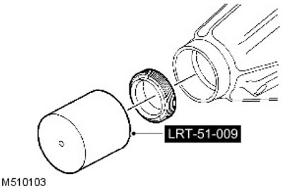
36. Using tool LRT-51-009, install the drive gear seal.
37. Install spacer and rear bearing correctly.
38. Install pinion gear, flange and washer.
39. Install a new drive gear flange and tighten to 100 Nm.
40. Lightly grease differential bearings.
41. Make sure that the pins are located in the bearing caps.
42. Install the differential bearing outer races and install the differential assembly into the crankcase.
43. Install the bearing caps and tighten the bolts to 10 Nm.
44. Screw on the adjusting nuts, tighten the ring gear side nut to 22 Nm. Make sure the opposite nut is free.
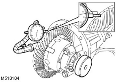
45. Install DTI to check ring gear backlash. Adjust the opposite nut to obtain the correct ring gear backlash.
46. Rotate the ring gear in both directions until the bearings are in a stable position.
47. Measure the backlash of the ring gear in three positions, adjust if necessary.
NOTE: Ring gear backlash should be between 0.076mm - 0.177mm.
48. Align the slots on the adjusting nuts with the nearest pin hole. Do not loosen nuts to align.
49. Tighten the bearing cap bolts to 180 Nm.
50. Secure the adjusting nuts with new roll pins.
51. Apply special paint to the ring gear teeth to check the contact patch.
52.
NOTE: Apply an assembly torque while turning to check the contact patch. The total turning torque must not exceed 10.85 Nm.
Rotate the gear a few times to get a full contact patch.
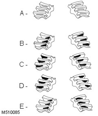
- 1. A = Contact pattern on the transmission side: this contact pattern must be centered on the gear teeth. The contact patch during coasting should be centered on the gear teeth, but may be displaced towards the inner end of the tooth flank. There should be some gap between the contact patch and the top of the tooth.
- 2. B = Correct side clearance: Thinner shim required.
- 3. C = Correct side clearance: Thicker shim required.
- 4. D = Correct pinion shim: Reduce backlash.
- 5. E = Correct pinion shim: Increase backlash.
53. Install differential assembly.
Comments on this article