Disassembly
1.
NOTE: *This procedure only applies to 110 models up to and including the following VINs:
- 110 without ABS -638163
- 110sABS -638248
Remove the differential assembly.
2. Mount the differential assembly in a vise or stand.
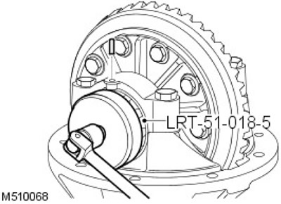
3. Knock out the adjusting nut roll pins using LRT 51-018/5 to release the adjusting nuts.
4. Mark the bearing caps for ease of assembly.
5. Turn out bolts of fastening of covers of bearings and remove covers.
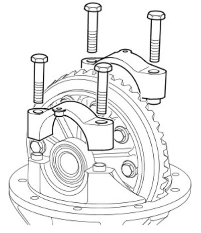
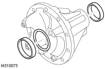
6. Remove the ring gear assembly and bearing outer races.
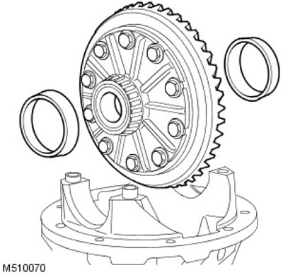
7. For ease of assembly, mark the outer races of the bearings if the bearings are to be reused.
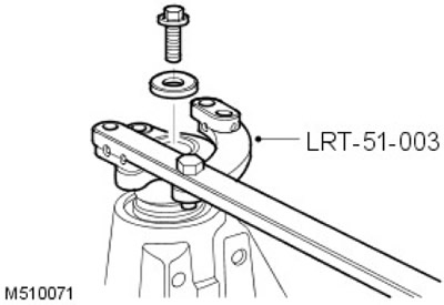
8. Using tool LRT-51-003 to hold the pinion flange, remove the bolt and washer.
9.
NOTE: Older front differentials have a square flange and an additional spacer. This spacer must be removed. Later versions of the front differential have a round flange but no spacer.
Remove the drive gear flange.
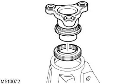
10.
CAUTION: Be careful not to damage the oil seal groove.
Using a lever, remove the gear oil seal.
11. Carefully remove the gear from the crankcase along with the rear bearing.
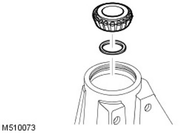
12. Remove the gear rear bearing shim and note the shim size.
13. Using a puller, remove the drive gear front bearing.
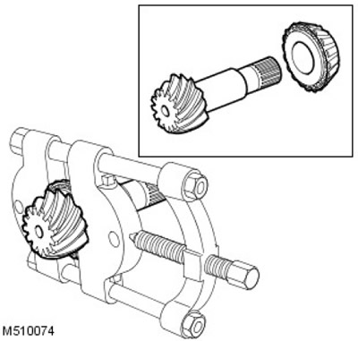
14. Remove the pinion bearing rings.
15. Remove the gear front bearing shim and note the shim size.
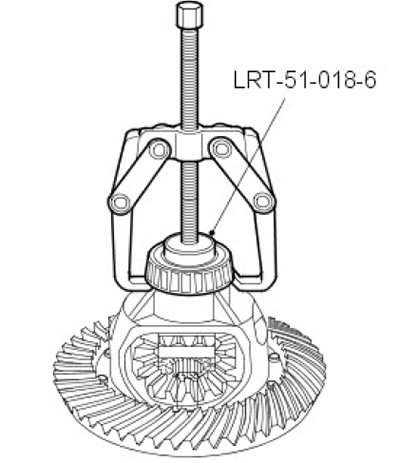
16. Using a two-arm puller and LRT 51-018/6, remove the differential bearings.
17. Secure the ring gear assembly in a vise.
18. Remove and discard the 10 ring gear to carrier bolts.
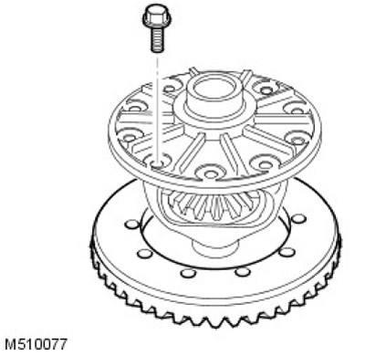
19. Carefully remove the ring gear from the carrier.
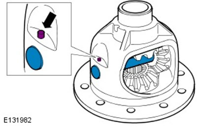
20.
NOTE: For vehicles with 4mm roll pin.
Remove and discard the axle roll pin in the carrier and remove the axle.
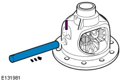
21.
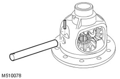
NOTE: For vehicles with 6mm roll pin.
Press out the cross shaft and cut the pin. Mount the planetary gear housing in a press using suitable vee shims and press out the cross shaft.
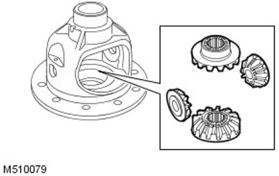
22. Turn the gears to the open part of the carrier and remove the satellites.
23.
NOTE: If the planetary housing has a 4mm roll pin hole for the cross shaft, discard the planetary housing and replace it with a housing with a 6mm roll pin hole.
Remove the sun gears.
24. Clean and inspect all components for wear and damage.
Assembly
1. Install the satellites and turn them to align the axle holes.
2. Install the axle, properly aligning the pin hole.
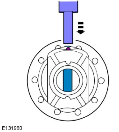
3.
NOTE: Fully press roll pin into planetary housing (after proper installation, approximately 8-10 mm will protrude from the housing).
Press the pin into the planetary gear housing.
4. Secure the axle with a new roll pin.
5. Install the ring gear in the carrier, screw in new bolts and tighten them to 60 Nm.
6. Clean and deburr the original front bearing shim. Install under the bearing ring.
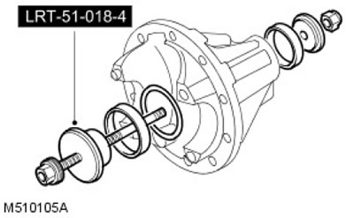
7. Clean the pinion bearing outer race grooves and remove any burrs. Using LRT 51-018-4, install the rear and front bearing races.
8. Install the front bearing on the drive gear.
9. Apply a thin coat of oil to the bearings.
10. Clean and deburr the original rear bearing shim. Install under the bearing ring.
11. Install the drive gear and drive gear rear bearing.
12. Install drive gear flange, washer and bolt.
13. Use LRT-51-003 to hold gear flange.
14. Tighten the pinion flange bolt to 100 Nm.
15. Check the gear for end play. If the reading is zero.
16. Rotate the gear several times until the bearings are in a stable position. Check the torque of the drive gear. The turning moment should be recorded when turning the gear. The turning torque of the drive gear should be 4 - 6 Nm.
17.
NOTE: To increase torque, install a narrower spacer. To reduce turning torque, install a wider spacer.
Adjust the size of the rear bearing shim to get the correct torque (approx. 0.025 mm = 1 Nm).
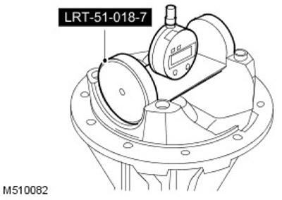
18. Install the LRT-51-018/7 tool on a flat plate and zero the DTI reading.
19. Ensure that the gear height adjustment block, indicator, and mating surfaces are clean and free of any burrs.
20. Mount the adjusting block LRT 51-018/1 on the gear head, correctly positioning it in the required position.
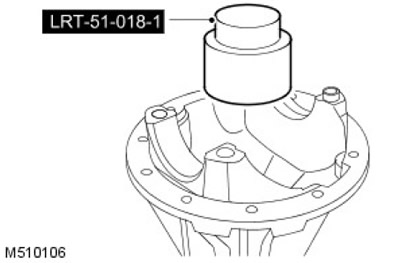
21.
CAUTION: The height of the adjusting block should be checked against the numbers printed on the side of the block.
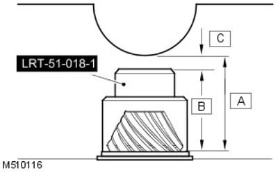
Gear height adjustment procedure: 'C' = 'A' - 'B'. Subtract nominal gear height 'A' from adjuster block height 'B' (on the side of the control block). Example: 74.390 - 73.130 = 1.26 mm Therefore the gear head height reading is -1.260 mm±0.025 mm.
- 1. 'A' = Nominal gear height, 74.390.
- 2. 'B' = Adjustment block height.
- 3. 'C' = Head height.
22. Mount the indicator LRT -51-018/7 on the adjusting block and shake it to get the minimum reading. If the reading is lower than required, reduce the shim size. If the reading is higher than required, increase the shim size.
23. Using tool LRT-51-003 to hold the pinion flange, remove the bolt and washer. Remove the drive gear flange.
24. Remove the drive gear, rear bearing and rear bearing shim.
25. Remove the outer race and shim of the gear front bearing. Discard the adjusting shim. Clean the groove of the bearing ring and deburr it.
26. Install a spacer of the required thickness and, using LRT 51-018/-4, install the front bearing outer race.
27. Install the pinion gear, rear bearing and rear bearing shim.
28. Install drive gear flange, washer and bolt. Using LRT-51-003 to hold the pinion flange, tighten the bolt to 100 Nm.
29. Rotate the gear in both directions until the bearings are in a stable position.
30. Check again the torque of the gear and adjust if necessary.
31. Check the height of the gear head again.
32. Using tool LRT-51-003 to hold the pinion flange, remove the bolt and washer. Remove the drive gear flange.
33. Reject the bolt.
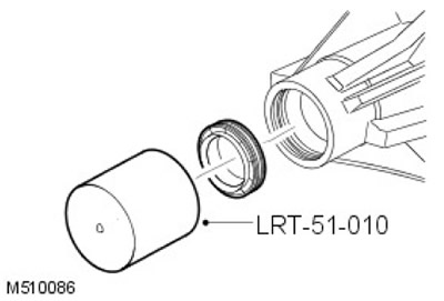
34. Using tool LRT-51-010, install the drive gear seal.
35. Install spacer and rear bearing correctly.
36. Install pinion gear, flange and washer.
37. Install a new drive gear flange and tighten to 100 Nm.
38. Lightly grease differential bearings.
39. Make sure that the spring-loaded pins are located in the bearing caps.
40. Install the differential bearing outer races and install the differential assembly into the crankcase.
41. Install the bearing caps and tighten the bolts to 10 Nm.
42. Screw on the adjusting nuts, tighten the ring gear side nut to 22 Nm. Make sure the opposite nut is free.
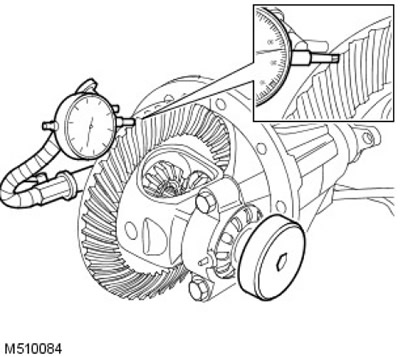
43. Install DTI to check ring gear backlash. Adjust the opposite nut to obtain the correct ring gear backlash.
44. Rotate the gear in both directions until the bearings are in a stable position.
45.
NOTE: Ring gear backlash should be between 0.076mm - 0.177mm.
Measure in three places to get the correct ring gear backlash.
46. Align the slots on the adjusting nuts with the nearest pin hole. Do not loosen nuts to align.
47. Tighten the bearing cap bolts to 90 Nm.
48. Secure the adjusting nuts with new roll pins.
49. Apply special paint to the ring gear teeth to check the contact patch.
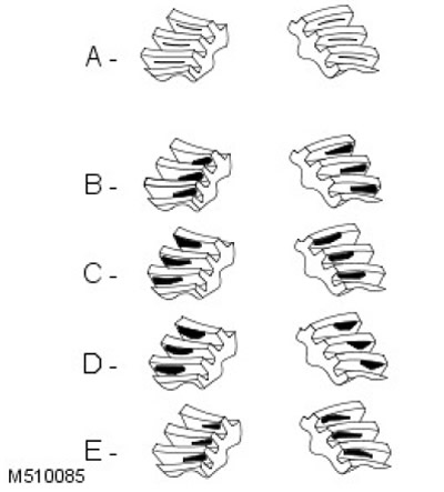
50.
NOTE: Apply an assembly torque while turning to check the contact patch. The total turning torque must not exceed 10.85 Nm.
Rotate the gear a few times to get a full contact patch.
- 1. A = Normal contact pattern: The contact pattern on the drive gear must be centered on the gear teeth. The contact patch on the driven gear should be centered on the gear teeth, but may be offset towards the inner end of the tooth flank. There should be some gap between the contact patch and the top of the tooth.
- 2. B = Incorrect side clearance: Thinner shim required.
- 3. C = Incorrect side clearance: Thicker shim required.
- 4. D = Incorrect pinion shim: Reduce backlash.
- 5. E = Incorrect pinion shim: Increase backlash.
51. Install differential assembly.
Comments on this article