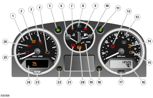
Location of components
| Pos. | spare no | Name |
| 1 | parts | Tachometer |
| 2 | - | Glow plug activation indicator |
| 3 | - | Seat belt indicator (only for Gulf countries) |
| 4 | - | Malfunction indicator (MIL) |
| 5 | - | Left turn indicator |
| 6 | - | Coolant temperature gauge (ECT) |
| 7 | - | ECT high temperature indicator |
| 8 | - | High Beam Indicator |
| 9 | - | Alarm indicator |
| 10 | - | Fuel gauge |
| 11 | - | Right turn indicator |
| 12 | - | Traction control indicator |
| 13 | - | Speedometer |
| 14 | - | Differential lock indicator |
| 15 | - | Rear fog light indicator |
| 16 | - | Odometer and odometer display |
| 17 | - | Odometer reset button |
| 18 | - | trailer indicator |
| 19 | - | Low fuel warning light |
| 20 | - | ABS indicator light (ABS) |
| 21 | - | Brake Warning Light |
| 22 | - | Parking light indicator |
| 23 | - | Anti-theft indicator |
| 24 | - | Transfer case low range indicator |
| 25 | - | Ignition indicator/charging circuit malfunction |
| 26 | - | Low oil pressure indicator |
Brief information
The instrument panel is located on the instrument panel, above the steering column. On the instrument panel are analog gauges and indicator lamps showing the status of the systems.
Analog pointers
The following analog indicators are installed on the instrument panel:
- Speedometer
- Tachometer
- Fuel gauge
- ECT pointer
Each analog pointer is driven by an electronic stepper motor. The characteristics of this engine dampen the vibrations of the instrument arrows. All indicators return to the zero position when the ignition is turned off.
Indicators
The indicators are located in different places on the instrument panel and can be divided into two groups: those controlled by the instrument panel electronic unit and those controlled by electronic control units of other vehicle systems.
The internally controlled indicators are activated according to the instrument panel's own software.
Power for indicators controlled by electronic control units of other vehicle systems comes from their respective systems. Indicators related to the engine and controlled by electronic control units of other vehicle systems are illuminated by the instrument panel when a message is received on the high-speed bus of the controller network (CAN) from the engine control unit (ECM).
The table below describes the indicators, whether they are checked when the ignition is turned on, and how they are controlled (internal or external).
| signaling device | Backlight color | Lamp test | with internal control (S) /with external control (E) |
| Glow plugs activated | Amber | No (may light up when the ignition is switched on, indicating that the glow plugs are activated) | E |
| Safety belt | Red | No | E |
| (MIL (malfunction signaling device)) | Amber | * Yes | E |
| Left Turn Signal | Green | No | E |
| High Temperature ECT | Red | Yes | S |
| high beam | Blue | No | E |
| Alarm | Red | No | E |
| Right turn signal | Green | No | E |
| Traction control | Amber | Yes | E |
| Differential lock | Amber | No | E |
| Rear fog lamp. | Amber | No | E |
| Trailer | Green | No | E |
| Low fuel warning lamp | Amber | Yes | S |
| **ABS | Amber | * Yes | E |
| Brake warning light | Red | Yes | E |
| turning on side lights; | Green | No | E |
| Anti-theft alarm system | Red | No | E |
| Switching on the low gear of the transfer case | Green | No | E |
| Ignition / charging circuit malfunction | Red | No | E |
| Low oil pressure | Red | No | E |
* = Lamp testing is performed by the subsystem module, not the instrument panel.
**= After replacing the ABS unit (anti-lock braking system) In MY 2011 vehicles, the hardware of the IPC unit has been modified to update the chip input signals to match the differences between WABCO and Bosch units. IPC compensates for the difference in the logic of operation, so the system does not require the intervention of the owner. The indicator will remain on in the event of a high or low voltage signal corresponding to an open circuit (O/S) or short circuit (S/C). Since ABS is not installed on all cars, a PID recorder is provided on the instrument panel to detect the presence of ABS. The default state is the presence of ABS in the new data packet. Therefore, if a new IPC unit needs to be installed on the vehicle, since the vehicle is NOT equipped with ABS, the ABS warning light will remain on until the PID logger is set to «ABS not installed». If your vehicle has an ABS system, the warning light should come on for three seconds and then turn off (routine check procedure).
Control scheme: sheet 1 of 2
NOTE: A = Rigid connection; D = High speed CAN bus
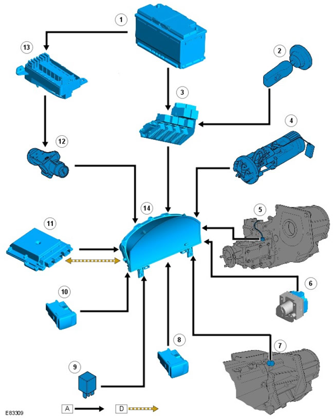
| Pos. | spare no | Name |
| 1 | parts | Accumulator battery |
| 2 | - | Light switch |
| 3 | - | central fuse box (CJB) |
| 4 | - | Fuel tank unit |
| 5 | - | Differential lock switch |
| 6 | - | ABS module |
| 7 | - | Reverse switch |
| 8 | - | Hazard light switch |
| 9 | - | Hazard light relay |
| 10 | - | Heated rear window switch |
| 11 | - | (The engine control unit (ECM)) |
| 12 | - | ignition switch |
| 13 | - | battery junction box (BJB) |
| 14 | - | Dashboard |
Control scheme: sheet 2 of 2
NOTE: A = wired connection
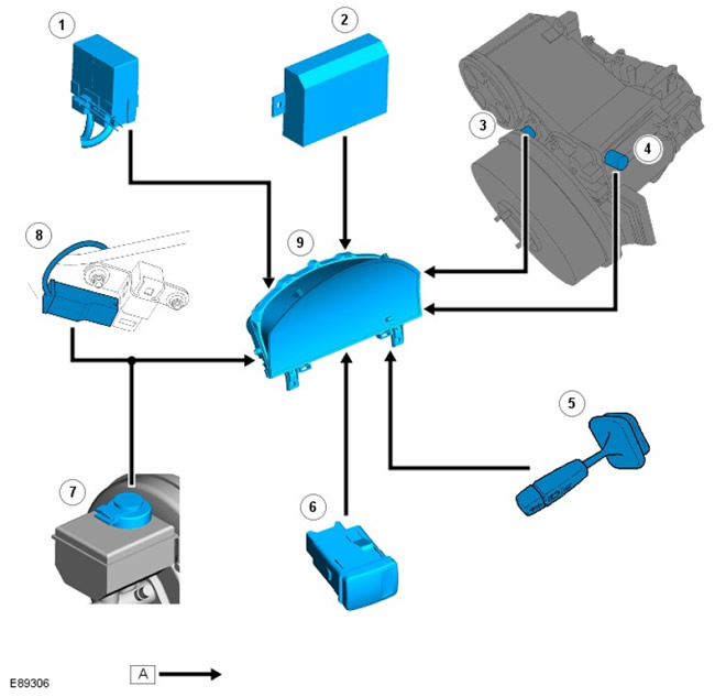
| Pos. | spare no | Name |
| 1 | parts | Heated windshield timer block |
| 2 | - | Anti-theft alarm control unit |
| 3 | - | Vehicle speed sensor |
| 4 | - | High/low range switch |
| 5 | - | Steering column switch: direction indicators |
| 6 | - | Rear fog light switch |
| 7 | - | Brake fluid level contact sensor |
| 8 | - | Parking brake switch |
| 9 | - | Dashboard |
Operating principle
Speedometer
The instrument panel receives a wired vehicle speed signal from the vehicle speed sensor. The vehicle speed sensor is a Hall effect sensor located in the transfer case. The sensor acts on the impulse wheel, which is located on the rear output shaft of the transfer case. For more information, see the chapter: Transfer case - The vehicle is equipped with: MT82 6-speed manual gearbox (308-07A Transfer box - Diesel engine ID4 2.4L, Description and operation).
Tachometer
The tachometer is driven by the engine speed signal transmitted over the high speed CAN bus from the ECM. This signal is determined by the readings of the crankshaft position sensor (CKP). The signal goes to the instrument panel microprocessor, and the output signal from the microprocessor drives the tachometer.
Fuel gauge
The instrument panel calculates the amount of fuel in the tank by applying a reference current to the fuel level sensor in the tank. The fuel level sensor uses a passive magnetic position sensor to measure the amount of fuel in the tank (MAPPS) float action.
The instrument panel measures the output signal received from the sensor, which is proportional to the level of the float lever and, accordingly, the amount of fuel in the tank. The instrument panel monitors the signal from the sensor at intervals of about 20 seconds. This prevents the pointer needle from constantly moving due to the movement of fuel in the tank during cornering or braking.
Coolant temperature gauge
The ECT indicator is driven by messages sent over the high speed CAN bus from the ECM. At normal operating temperature, the pointer pointer is in the center of the display. Different positions of the arrow correspond to their temperature values.
| Coolant temperature,°C (°F) | Pointer arrow position |
| Ignition off | Park position (parking) |
| 40 (104) | Low temperature (blue segment) |
| 75 - 115 (167 - 239) | normal temperature (in the center) |
| 120 (248) | Elevated temperature (red segment) |
| 125 (257) | Overheat |
Glow plug activation indicator
The glow plug activation indicator is turned on by the instrument panel software when a high speed CAN·message is received from the ECM. The indicator lights up amber when the ignition is switched to position II. The period of activation of the indicator depends on the ECT and if the temperature of the ECT is high, the indicator does not turn on.
The indicator is controlled by messages from the ECM on the high-speed CAN bus, which are received simultaneously with the activation of the glow plugs to preheat the combustion chambers. When the glow plugs are warmed up, the indicator goes out, indicating that the engine can now be started.
Seat belt indicator
The seat belt indicator is controlled by a wired power line from switches located in the front seat belt buckles. The seat belt indicator is only installed on vehicles for the Gulf countries.
Malfunction indicator
The MIL is controlled by the instrument panel software when messages are received from the ECM over the high speed CAN bus. The warning light comes on during a lamp test performed by the ECM when the ignition is switched to position II. After starting the engine, the indicator goes out.
If the MIL stays on after starting the engine or comes on while driving, this indicates a problem that needs to be identified and repaired as soon as possible.
Turning on the MIL indicator indicates a malfunction of the on-board diagnostic system (OBD), leading to an increase in emissions.
Indicators for left and right turn indicators
The direction indicators are controlled by the instrument panel software when receiving wired signals from the steering column switch. When the direction indicator is turned on, the instrument panel receives a signal from the steering column switch. The instrument cluster controller sets the green flashing rhythm. During normal operation, the turn signal flashes slowly. Flashing is accompanied by an audible signal from the instrument panel annunciator. In the event of a malfunction, the indicator will start flashing at double speed.
High coolant temperature indicator
The ECT high temperature indicator turns on when a message is received from the ECM on the high speed CAN bus. The indicator turns on when the ignition is switched to position II during the three-second lamp test and goes out when the engine is started. If the indicator turns on while driving, this indicates a malfunction in the engine cooling system - the engine must be stopped as soon as possible.
High Beam Indicator
The high beam indicator is controlled by the instrument cluster software when it receives a wired signal from the CJB. The signal from the CJB is generated by the steering column switch when the high beam is on.
Alarm indicator
The hazard indicator is controlled by the instrument panel software when a wired signal is received from the hazard warning light switch. The alarm indicators can work when the ignition is off, while the right and left turn indicators are activated simultaneously.
Traction control indicator
The traction control indicator is controlled by the instrument panel software when a wired signal is received from the ABS module. The indicator comes on for three seconds during the lamp test when the ignition is switched to position II. If no malfunction is detected, after the end of the test time, the indicator goes out.
When the traction control system is on, the indicator flashes to notify the driver that the system is adjusting the engine's power output.
Heated windshield indicator
The engine must be running to turn on the heated windshield. The instrument panel receives a signal from the ECM over the high speed CAN bus to confirm that the engine is running. When this message is received, the instrument panel generates a wired signal to the heated windshield relay. When the heated windshield is subsequently requested to be switched on, a ground circuit is created via the heated windshield switch. When the instrument panel detects this circuit, it turns on the heated windshield indicator.
Differential lock indicator
The differential lock indicator turns on when a wired signal is received from the differential lock switch. The indicator comes on every time the differential lock is selected and the ignition is switched to position II.
Rear fog light indicator
The rear fog light indicator turns on when it receives a wired signal from the rear fog light switch. The indicator comes on every time the rear fog lamps are switched on and the ignition is switched to position II.
Trailer indicator
The trailer indicator is controlled by the instrument cluster software when it receives a wired signal from the hazard warning light relay. When a trailer is connected, the hazard warning light relay is energized and sent to the instrument panel. Power through the hazard warning light relay is generated by the steering column switch. The instrument cluster controller sets the green flashing rhythm. The trailer indicator flashes slowly. The blinking is accompanied by an audible signal from the instrument panel annunciator, coinciding with the operation of the direction indicators.
Low fuel warning light
The instrument panel calculates the amount of fuel in the tank by applying a reference current to the fuel level sensor in the tank. If the instrument panel determines that the fuel level in the tank is at 14 liters (3.69 gallons) or less, the low fuel indicator will come on and the horn will sound. For more information, see «Fuel gauge» higher.
ABS indicator
The ABS indicator is controlled by the ABS module, which sends a wired signal to the instrument cluster. The indicator illuminates amber during a three-second lamp test performed by the ABS module when the ignition is switched to position II. If the warning light stays on after starting the engine or comes on while driving, the ABS system is faulty and the ABS function is cancelled.
The ABS module will alert the driver when a DTC is stored in the memory (DTC) while checking lamps. The warning will be implemented as follows:
- turning on the indicator for 0.5 seconds;
- turning off the indicator for 0.5 seconds;
- turning on the indicator for 2 seconds.
If the indicator turns on due to a sensor fault, it remains on the next time the ignition is turned on, even after the fault has been corrected. After accelerating the vehicle to a speed exceeding 20 km/h (12.5 mph), the indicator turns off. This procedure allows the ABS module to perform a thorough system test to make sure it works after the sensor has been replaced.
Brake Warning Light
The brake warning light comes on for 3 seconds during the lamp test when the ignition is switched to position II. The indicator also turns on when the parking brake is applied or the brake fluid level drops below a preset level. The instrument panel is directly connected to the parking brake switch and the brake fluid level switch, which are connected in parallel. If one of the above conditions is met, a ground loop is created that includes a signaling device.
Parking light indicator
The side light indicator is controlled by the light switch. When the switch is moved to the position lamps or the headlights on position, wired power is supplied through the CJB to the instrument panel. When wired power is supplied, the instrument panel turns on the indicator.
Anti-theft indicator
The activation of the anti-theft alarm indicator is controlled directly by the anti-theft alarm control unit. For more information, see the chapter: Anti-theft system - active (419-01A Anti-theft system - active, Description and principle of operation), Anti-theft system - passive (419-01B Anti-theft system - passive, Description and function).
Transfer case low range indicator
The transfer box high/low range switch is directly connected to the instrument panel. When low range is selected, the transfer case energizes the instrument panel, after which the green low range indicator turns on. The low range indicator remains on until high range is selected and power is removed from the high/low range switch.
Ignition/Charging Circuit Malfunction Warning Light
The Ignition/Charging Circuit Fault indicator is illuminated by the instrument cluster software when a message is received from the ECM on the high speed CAN bus. The indicator turns red when the ignition is switched to position II and goes out when the engine is started.
If the indicator does not turn off after starting the engine or lights up while the vehicle is moving, this means that as a result of a malfunction, the battery is not being recharged from the alternator.
Low oil pressure warning light
The low oil pressure indicator is turned on by the instrument panel software when a message is received from the ECM on the high speed CAN bus. The indicator lights up red when the ignition is switched to position II. When the engine is turned on and the oil pressure increases, the indicator should go out. If the indicator does not turn off after starting the engine or lights up while the vehicle is moving, the vehicle must be stopped as soon as possible and the engine must not be turned on until the malfunction is corrected.
Instrument panel replacement
When installing a new instrument panel, connect the vehicle to a Land Rover approved diagnostic system and follow the appropriate procedure to replace the instrument panel. This ensures that the coded vehicle data is correctly set in the instrument cluster. The Land Rover approved diagnostic system will also record the current service interval and restore the settings in the new instrument cluster.
Comments on this article