Contents: Arrangement of elements ⇩ Arrangement of elements ⇩ Review ⇩ Description - model SVX (60th…⇩ Control scheme ⇩ Control scheme ⇩
Arrangement of elements
Models from 2007 model year onwards (except SVX model) (60th anniversary)
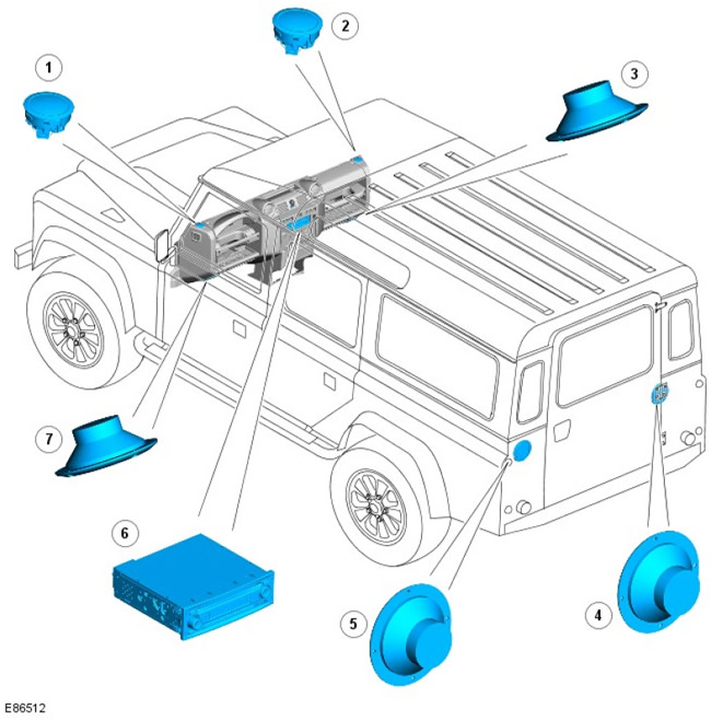
| Pos. | Spare part number | Name |
| 1 | - | Front Left (LH) High Range Speaker |
| 2 | - | Front Right (RH) High Range Speaker |
| 3 | - | Front (right) mid-range speaker |
| 4 | - | Rear right midrange speaker |
| 5 | - | Rear (left) mid-range speaker |
| 6 | - | Main audio unit |
| 7 | - | Front left midrange speaker |
Arrangement of elements
Model SVX (60th anniversary)
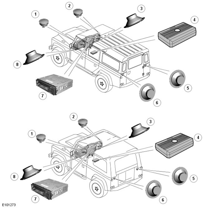
| Pos. | Spare part number | Name |
| 1 | - | Front LH high range speaker |
| 2 | - | Front Right High Range Speaker |
| 3 | - | Front right midrange speaker |
| 4 | - | Subwoofer |
| 5 | - | Rear right midrange speaker |
| 6 | - | Rear left midrange speaker |
| 7 | - | Head unit of the audio system |
| 8 | - | Front left midrange speaker |
Review
The audio system includes a CD tuner unit that supports up to 6 speakers. The audio system head unit is located in the center of the instrument panel. The head unit includes the following units:
- AM/FM radio
- Music CD player
- MP3 CD Player
- RDS traffic information receiver
The audio system does not have diagnostic functions and is not connected to other vehicle systems.
Model SVX (60 th Anniversary)
The SVX model has an upgraded head unit, speakers and a subwoofer. The main audio unit has an additional universal serial bus (USB)-pa3beM and is also compatible with MP3/WMA format.
The 90 also comes with two additional speakers located in the rear cargo area.
Description - model SVX (60th anniversary)
Clarion® DB568RUSB Main Unit
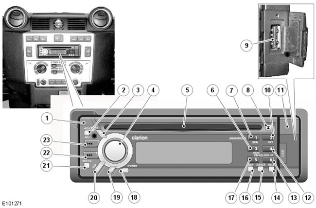
| Pos. | Spare No | Name |
| 1 | parts | Removable control panel release button |
| 2 | - | Auto Frequency (AF) button |
| 3 | Preset scan button/ Auto-save - Radio mode or play/ pause in playback - CD (CD)/MP3/WMA/USB mode | |
| 4 | - | Rotary volume control and function selection |
| 5 | - | CD Input/Eject Button |
| 6 | - | Preset/Save 3 button - Radio mode or Random Play (RDM) button - CD/MP3/WMA/USB mode |
| 7 | - | Preset/Save 1 button - Radio mode or Scan (SCN) button - CD/MP3/WMA/USB mode |
| 8 | - | CD eject button |
| 9 | - | USB port |
| 10 | - | Preset/Save 2 button - Radio mode or Repeat button - CD/MP3/WMA/USB mode |
| 11 | - | USB Port Tiny |
| 12 | - | Preset/Save Button 4 - Radio Mode |
| 13 | Station preset/store button 6 or folder select button UP for MP3/WMA/USB folder options and for CD-DA or MP3/WMA selection on multi-session disc | |
| 14 | - | Title display - MP3/WMA/USB mode |
| 15 | - | 'Z' sound enhancer function button |
| 16 | - | Display change button |
| 17 | Station preset/store button 5 or folder down (DN) button for MP3/WMA/USB folder options and for CD-DA or MP3/WMA selection on multi-session disc | |
| 18 | - | Power on/off and mode selection button |
| 19 | - | Traffic Messages Button |
| 20 | - | Band switching/automatic search/manual search - radio mode or play first track - CD/MP3/WMA/USB mode |
| 21 | Audio mode (bass/treble/left-right speaker balance/front-rear speaker balance) or Magna bass selection mode | |
| 22 | - | Select station - radio mode or select "track" forward - CD/USB mode or fast forward - CD/USB mode |
| 23 | - | Select station - radio mode or select "track" back - CD/USB mode or fast scroll back - CD/USB mode |
The head unit is located in the center of the instrument panel, above the heater controls. The head unit is housed in an ISO standard radio housing, which is specific to the Clarion® head unit. Two special tools are required to remove the head unit from the housing after installation.
The Interconnect Harness is used to connect the Clarion® head unit to the existing electrical connectors on the In-Car Entertainment (ICE) wiring harness. The Interconnect Harness plugs into the existing ICE connector on the head harness and has four output plugs and one connector for connections to the Clarion® head unit. The output plugs serve as speaker outputs and are coloured red and white. Two of the wires on the plugs have a blue tracer for identification purposes. The two output plugs plug into the two upper player sockets on the head unit and the two output plugs with a blue tracer plug into the two central player sockets on the head unit. The player sockets on the head unit are also coloured red and white to ensure correct connections and correct speaker polarity. The connector also plugs into the back of the head unit. The antenna connector is a male type; it is inserted into the socket on the back of the main unit.
If iPod connectivity is available, an optional iPod Audio Connection Module and jumper harness is used. The Audio Connection Module is located on the cabin cross member to the right of the main unit and is secured with a tie wrap. This harness connects to the existing ICE connector and the jumper harness connects to the iPod Audio Connection Module jumper harness. The Audio Connection Module has an antenna lead. The antenna lead connects to the antenna connector on the module and the antenna lead from the module then connects to the antenna connector on the main unit.
The Clarion® DB568RUSB main unit features a control panel that can be removed for theft protection. To release the panel, press the button in the upper (left) corner of the unit. The panel will be released and can be removed and stored in the included case. To replace the panel, insert the right edge of the panel into the slots in the main unit and gently push the left edge of the panel towards the unit until the latch engages.
The USB port is located on the (right) edge of the unit and can be accessed by opening the cover on the removable control panel. This port allows the client's flash card to be used to listen to a large number of MP3 and WMA music files. The unit can read the files, as well as the folder structure and data from the "flash drive" and play music directly through the USB port. It is not recommended to use this port to connect an iPod.
Complete operating instructions and a detailed description of the unit's functions are provided in the owner's literature supplied with the vehicle.
An additional input jack is located inside the storage compartment. This jack allows you to additionally connect an MP3 player or other device via a single-pole plug.
Technical specifications:
- Supply voltage: 14.4V (permissible 10.8 - 15.6 V) - grounding to "mass"
- Current: less than 15 A
- Speaker impedance: 4 Ohm (4 - 8 Ohm is acceptable)
- Maximum audio output power: 200 W (50W for 4 speakers)
- Audio output power: 4 x 25 W
- Compatible with USB 1.1 and 2.0 with a transfer rate of 12 Mbps maximum
- Compatible with MP3 and WMA
- FM range: 87.5 - 108 MHz
- MW range: 531 - 1602 kHz
- AM range: 153 - 279 kHz
The speakers installed in the SVX are based on the standard units with the necessary improvements and are also supplied by Clarion®. These speakers connect to the existing speaker wiring harnesses using jumper wires that allow the use of the various connectors required by the Clarion® speakers.
Clarion SRV313 Subwoofer
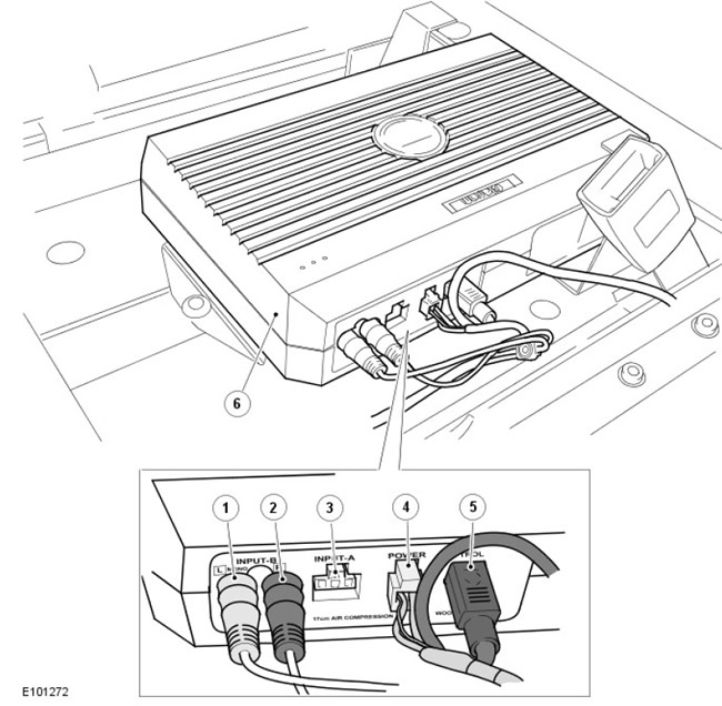
| Pos. | Spare part number | Name |
| 1 | - | Input (left) speaker |
| 2 | - | Input (right) speaker |
| 3 | - | Not used |
| 4 | - | Power and ground connector |
| 5 | - | Remote control connector |
| 6 | - | Subwoofer unit |
The Clarion® SRV313 subwoofer is located on the cabin floor below the center storage compartment and is secured to the floor with two self-tapping screws.
The subwoofer is connected to the main unit via a connecting cable coming from the unit. The player's two connectors serve as inputs for the left and right speakers and are colored white and red, respectively, for identification purposes; the speakers are connected to the 'Input B' sockets ('Input A' socket is not used). The power socket supplies power and ground to the unit. The 'Remote Control' socket allows you to connect a remote control unit.
Remote control and additional socket
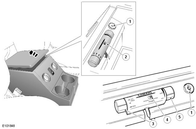
| Pos. | Spare part number | Name |
| 1 | - | Additional socket |
| 2 | - | Remote control |
| 3 | - | Frequency control |
| 4 | - | Phase switch |
| 5 | - | Volume control |
The remote control is located at the front of the storage compartment and can be accessed by removing the storage compartment cover. The remote control has a rotary control on the left end that allows you to adjust the subwoofer's low-frequency output by adjusting the low-pass filter cutoff frequency. There are four options to choose from: 50, 75, 100 and 120 Hz. The subwoofer will only output frequencies below the selected hertz level. The rotary control on the right end of the remote control adjusts the speaker gain and can be used to adjust the subwoofer's output volume, independent of the volume control on the main unit. A switch on the remote control allows you to switch the subwoofer's phase between normal and reverse. Clarion recommends using normal phase for this option.
Next to the remote control unit there is an additional input jack. This jack allows you to connect an additional audio source, such as an MP3 player.
Subwoofer specifications:
- 120W High Power Amplifier with Low Pass Filter
- 17cm counter drive woofer with dual neodymium magnet
- Compression block with cast aluminum housing
- Wired remote control for gain/low pass filter control (50, 75, 100 and 120 Hz to choose from)/ phase filter
- Dual 4 Ohm voice coils.
Control scheme
Models from 2007 model year onwards (except SVX model) (60th anniversary)
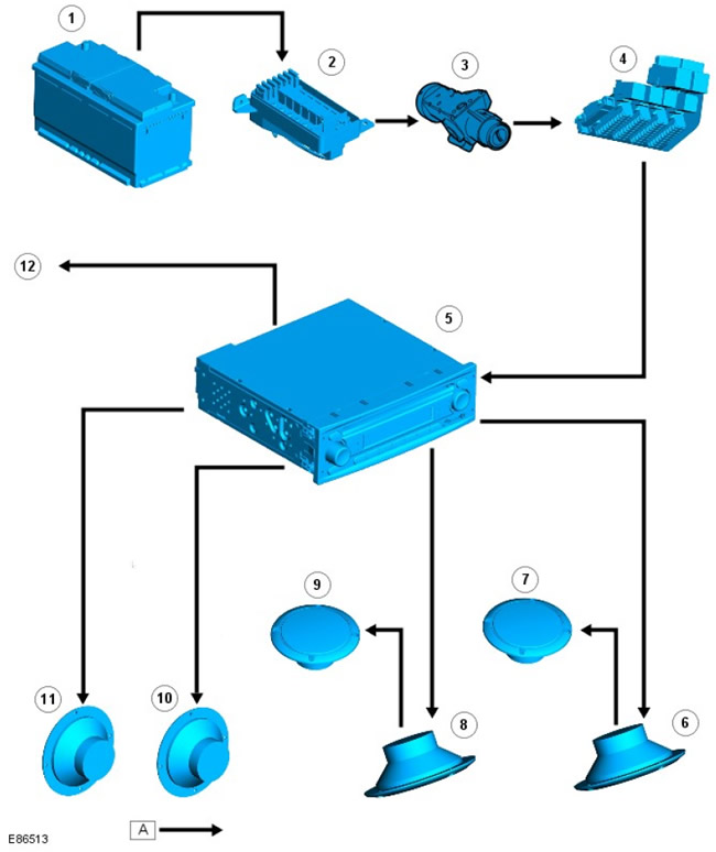
| Pos. | Spare No | Name |
| 1 | parts | Battery |
| 2 | - | battery Junction Box (BJB) |
| 3 | - | Ignition switch |
| 4 | - | central Junction Box (CJB) |
| 5 | - | Main audio unit |
| 6 | - | Front right midrange speaker |
| 7 | - | Front Right High Range Speaker |
| 8 | - | Front left midrange speaker |
| 9 | - | Front LH high range speaker |
| 10 | - | Rear right midrange speaker |
| 11 | - | Rear left midrange speaker |
| 12 | - | Antenna |
Control scheme
Model SVX (60th anniversary)
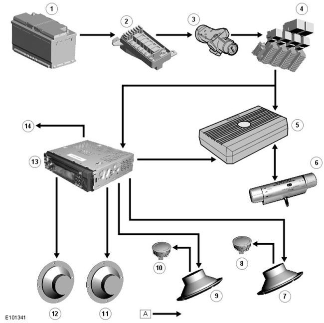
| Pos. | Spare No | Name |
| 1 | parts | Battery |
| 2 | - | BJB |
| 3 | - | Ignition switch |
| 4 | - | CJB |
| 5 | - | Subwoofer |
| 6 | - | Subwoofer Remote Control Unit |
| 7 | - | Front right midrange speaker |
| 8 | - | Front Right High Range Speaker |
| 9 | - | Front left midrange speaker |
| 10 | - | Front LH high range speaker |
| 11 | - | Rear right midrange speaker |
| 12 | - | Rear left midrange speaker |
| 13 | - | Head unit of the audio system |
| 14 | - | Antenna |
Comments on this article