Contents: Arrangement of elements ⇩ Review ⇩ Transceiver winding ⇩ Anti-theft protection system module ⇩ Engine control unit ⇩ Control scheme ⇩ Operating principles ⇩
Arrangement of elements
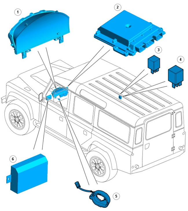
| Pos. | Spare part number | Name |
| 1 | - | Instrument panel |
| 2 | - | engine Control Module (ECM) |
| 3 | - | Starter relay |
| 4 | - | Glow Plug Relay |
| 5 | - | Transceiver winding |
| 6 | - | Anti-theft protection system module |
Review
The 10AS anti-theft system, together with the ECM, controls the operation of the passive anti-theft system. The passive anti-theft system immobilizes the engine by disabling the starter relay and fuel injectors until the correct RF remote control code is received.
The passive anti-theft system provides 2 levels of protection:
- Engine blocking only
- Engine blocking plus activation of perimeter and volume protection.
For more information, please refer to the chapter: Anti-theft system - active (419-01A Anti-theft system - active, Description and operating principle).
The theft deterrent module activates the immobilizer 30 seconds after the key is removed from the ignition and the driver's door is opened. If the key is removed from the ignition but the driver's door is closed, the theft deterrent module activates the immobilizer after 5 minutes.
Transceiver winding
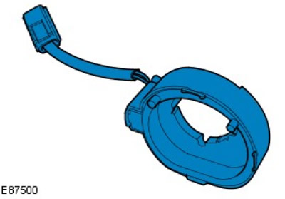
The transceiver winding is a coil on the ignition lock cylinder. When the ignition switch is turned to position II, the anti-theft module supplies direct voltage from the battery and alternating voltage to the transceiver winding. This creates a magnetic field around the ignition lock cylinder, which disappears and reappears in accordance with the pulsation of the power supplied by the anti-theft module. The pulsation of the magnetic field activates the remote control, which transmits the switching on signal.
Anti-theft protection system module
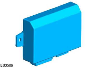
The anti-theft system module is located behind the instrument panel; together with the ECM, it controls the operation of the passive anti-theft system. The anti-theft system module receives DC voltage from the battery via the battery junction box (BJB) and ignition voltage via the central fuse box (CJB).
For more information, see the chapter: Battery and Wires (414-01 Battery, Battery Mount and Wires, Description and Operating Principle).
The activation code is transmitted to the anti-theft protection module from the remote control. The activation code is received by the antenna of the anti-theft protection module, which is located vertically under the module. The anti-theft protection module determines the authenticity of the code received from the remote control by comparing it with the sample in the device's memory.
The anti-theft system module also controls the following functions:
- active anti-theft system. For more information, see the chapter: Anti-theft system - active (419-01A Anti-theft system - active, Description and operating principle).
- central locking. For more information, see chapter: Handles, locks, latches and entry systems (501-14 Handles, Locks, Latches and Entry Systems, Description and Operation).
- interior lighting. For more information, see the chapter: Interior Lighting (417-02 Interior Lighting, Description and Operating Principle).
- emergency warning lights. For more information, see the chapter: Outdoor Lighting (417-01 Outdoor Lighting, Description and Operating Principle).
Engine control unit
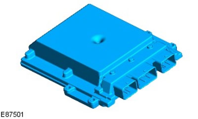
The ECM is mounted on the engine compartment bulkhead; together with the anti-theft system module, it controls the operation of the passive anti-theft system.
For more information, see the chapter: Electronic controls (303-14 Electronic Controls - ID4 2.4L Diesel Engine, Description and Operating Principle).
Control scheme
NOTE: A = rigid connection; D = High Speed CAN Data Bus (CAN)
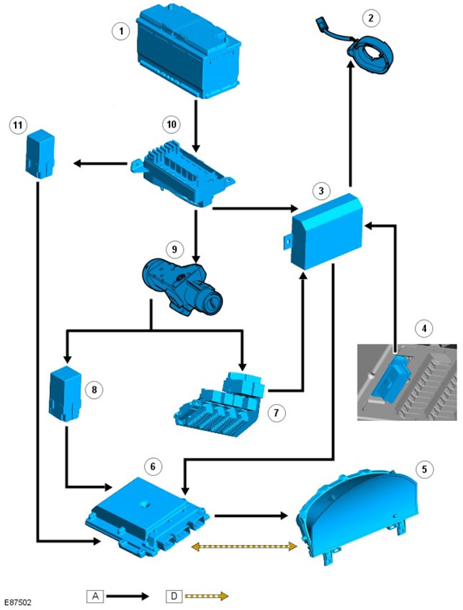
| Pos. | Spare part number | Name |
| 1 | - | Battery |
| 2 | - | Transceiver winding |
| 3 | - | Anti-theft protection system module |
| 4 | - | Diagnostic connector |
| 5 | - | Instrument panel |
| 6 | - | ECM |
| 7 | - | CJB |
| 8 | - | Starter relay |
| 9 | - | Ignition switch |
| 10 | - | BJB |
| 11 | - | Glow Plug Relay |
Operating principles
The anti-theft module receives constant power from the battery via fuse 7 in the BJB. When the key is inserted into the ignition switch and turned to position II (ignition on), the anti-theft system module is also powered via fuse 8 CJB.
When powered by the ignition switch coil, the anti-theft system module activates the transceiver coil by applying battery voltage from pin 12 of connector C0057 and AC voltage from pin 7 of connector C0057.
The alternating voltage from the anti-theft module causes the magnetic field generated by the transceiver coil to appear and disappear. The pulsating magnetic field activates the remote control, which transmits the activation code to the anti-theft module.
The theft deterrent module receives the arming code on its antenna. This code is compared with the value stored in memory. If the code matches, the theft deterrent module sends an arming signal to the instrument cluster. The instrument cluster acts as a gateway, converting the signal sent by the theft deterrent module into a signal that can be processed by the ECM. This signal is then sent by the instrument cluster to the eCm, which energizes the starter relay and fuel injectors, allowing the engine to start.
Emergency access with key
If the immobilizer is activated and the remote control is not present, the engine can be started by performing the emergency key access procedure. For information on emergency key access, see the Owner's Manual.
Comments on this article