Contents: Component arrangement ⇩ General Provisions ⇩ Anti-theft system indicator ⇩ Anti-theft system status indication ⇩ BBUS Siren (if any) ⇩ Penetration sensor (if any) ⇩ System operation ⇩ System activation ⇩ Incorrect actions when locking ⇩ Deactivation ⇩ Sounding the alarm ⇩ Sources of alarm signals ⇩ Vehicle transportation mode ⇩ Diagnostics ⇩ Error codes ⇩ Control system diagram ⇩
Component arrangement
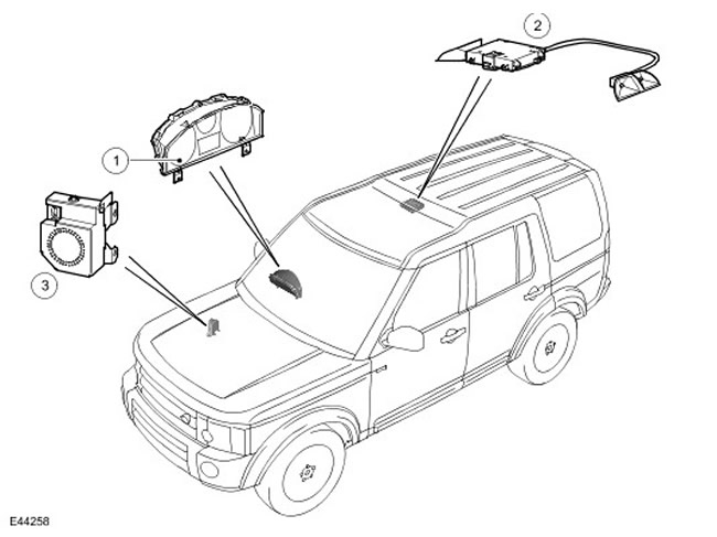
| Item name | Spare part catalog number | Description |
| 1 | - | Anti-theft alarm system |
| 2 | - | Penetration sensor |
| 3 | - | Self-powered alarm siren (BBUS) |
General Provisions
The security system monitors the condition of all hinged body panels for unauthorized opening. On some models, the anti-theft system monitors the interior volume of the car for penetration and changes in the position of the car body.
The anti-theft system is controlled by CJB (central switching unit). When the CJB alarm is triggered (central switching unit) includes vehicle horns or self-powered siren and hazard warning lights.
The anti-theft system consists of:
- Anti-theft system indicator.
- BBUS Siren (depending on the supply market).
- Penetration sensor (depending on the supply market).
- CJB Block (central switching unit).
- Limit switches under the hood, in the doors and in the tailgate opening. For more information, see Handles, Locks, Latches and Entry Systems (50114 Handles, Locks, Latches and Entry Systems)
- Car Horns For more information, please refer to Horn (413-06 Horn)
Anti-theft system indicator
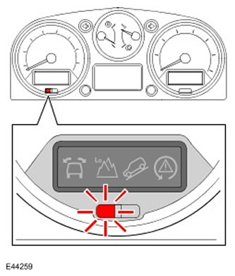
The alarm system indicator is a red LED (light-emitting diode) installed in the instrument panel and designed to visually indicate the status of the anti-theft system. The alarm operation is controlled by the CJB (central switching unit), which changes the LED blinking frequency depending on the status of the anti-theft system.
Anti-theft system status indication
| State | Description | Anti-theft system indicator |
| 0 - Deactivated | When the system is deactivated. And also during the first 10 seconds after the system is activated, if one of the protected body panels is open. | Turned off. |
| 1 - Activated | Switches on 10 seconds after the anti-theft alarm is activated. | Flash of 10 ms duration every 2 s. |
| 2 - Turning on the perimeter security(switching to standby mode) | All body panels are closed. The start of the system status indication is delayed by 2.5 seconds to allow time for the double locking command to be processed. | Double flash of 10 ms every 2 s for 10 s. |
| 3 - Activation of the ultrasonic penetration sensor | All body panels are closed and the intrusion sensor is activated. The start of the system status indication is delayed by 2.5 seconds to allow time for the double locking command to be processed. | Triple flash of 10 ms every 2 s for 10 s. |
BBUS Siren (if any)
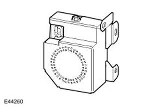
The BBUS siren is located in the engine compartment, next to the brake booster. The BBUS siren uses a built-in sound generator that produces a loud alarm signal when the anti-theft alarm is triggered. The BBUS unit is supplied with or without a body tilt sensor, depending on the country of sale. Externally, both BBUS sirens look the same.
The BBUS unit is controlled by the CJB (central switching unit). CJB Block (central switching unit) and the BBUS unit exchange signals via the LIN communication bus (local bus). Power for the BBUS siren is normally supplied by the constant battery power supply from the CJB. (central switching unit). In case of battery failure, the siren is powered by a rechargeable battery built into the signal.
When the active anti-theft system is in the perimeter protection mode or the interior protection mode, the CJB (central switching unit) sends an activation signal to the BBUS siren. When the active anti-theft alarm system is in the interior volume protection mode, the CJB (central switching unit) sends a signal to activate the body tilt sensor (if any). When activation signals are received, the siren and body tilt sensor respond with their status signal. If no response to activation signals is received within 12 seconds, the CJB (central switching unit) detects this as a malfunction and sends a deactivation signal to the siren or the tilt sensor, depending on which device is installed. The cJb unit (central switching unit) also logs associated fault codes.
If the anti-theft system is in standby mode with the siren deactivated, then when the alarm state is activated, the CJB unit (central switching unit) will use a car horn instead of a siren.
If the siren is activated, the CJB (central switching unit) sends periodic signals (clock pulse) to the BBUS unit, and the BBUS unit controls the battery power supply circuit and the communication line with the CJB unit (central switching unit). The BBUS siren is activated if:
- It receives an on signal from the CJB. (central switching unit) or a body tilt sensor.
- Communication line with CJB unit is broken (central switching unit) or food chains.
Penetration sensor (if any)
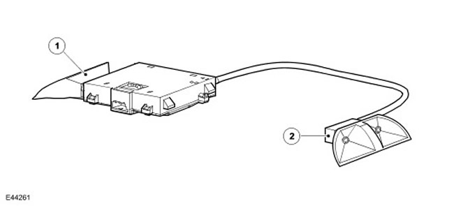
| Item name | Spare part catalog number | Description |
| 1 | - | Front pair "transmitter-receiver" |
| 2 | - | Rear pair "transmitter-receiver" |
The intrusion sensor is mounted in the housing on the roof in front of the second row seat interior light housing and monitors for intrusion into the passenger compartment when the anti-theft system is activated.
The intrusion sensor consists of a microcontroller, two acoustic transmitters and two acoustic receivers. One transmitter/receiver pair is oriented toward the front of the vehicle, and the other is oriented toward the rear. The front transmitter/receiver pair is housed in a rubber housing attached to the microcontroller housing. The rear pair is also housed in a rubber housing, remote from the microcontroller but connected to it via a four-wire cable.
Power for the intrusion sensor is supplied by the CJB. (central switching unit). CJB Block (central switching unit) activates and deactivates the intrusion sensor at the same time as activating and deactivating the interior volume protection mode. When the intrusion sensor is activated, its transmitters continuously generate ultrasonic pulses and then use the receivers to receive the pulses reflected from objects in the cabin to monitor changes in the profile of the passenger compartment. When a profile change is detected that indicates movement in the passenger compartment, the intrusion sensor sends an alarm signal to the CJB (central switching unit).
Each time the ultrasonic sensor is turned on, it performs a self-diagnosis procedure. If no faults are detected, the sensor sends a message to the CJB (central switching unit) confirmation signal. In case the CJB unit (central switching unit) did not receive a confirmation signal from the sensor, it turns it off.
System operation
CJB Block (central switching unit) automatically activates and deactivates the anti-theft system when the central locking system (CLS) is operated. For more information, see Handles, Locks, Latches and Entry Systems (501-14 Handles, Locks, Latches and Entry Systems)
System activation
If the vehicle is not equipped with an intrusion and body tilt sensor, the anti-theft system switches to perimeter protection mode when the locks are locked or double-locked.
If the vehicle is equipped with a break-in sensor, the anti-theft system can be activated in one of two modes:
- The perimeter security mode, when the system monitors only opening body panels, is activated when the car is locked with a remote control.
- The interior volume protection mode, when the system monitors the opening body panels, the interior volume and, if there is a tilt sensor, the position of the body. The interior volume protection mode is activated when the locks are set to the double locking position using the remote control.
- The driver's door is closed.
- A valid key is not in the ignition switch.
- The anti-theft system is not in the warning signal state.
- The anti-theft system is activated.
- CJB Block (central switching unit) is not in transport mode.
Incorrect actions when locking
If the driver's door is open when a lock or double lock signal is received, the anti-theft alarm system remains deactivated and the CJB (central switching unit) generates a signal about the impossibility of locking by briefly (100 ms) turning on the car's sound signals.
After receiving from the CJB unit (central switching unit) activation commands, the anti-theft system switches to perimeter protection mode, monitoring the state of all hinged body panels, and then, depending on the configuration, sends an activation signal to the BBUS unit. On vehicles equipped with an intrusion sensor, the CJB unit (central switching unit) enters the interior volume protection mode, sending activation signals to the intrusion sensor and the body tilt sensor. After the command to activate the intrusion sensor is sent, the CJB unit (central switching unit) ignores sensor signals for 30 seconds so that the sensor can accurately determine the internal volume.
If any hinged body panel, except the tailgate, is open, the CJB (central switching unit) activates the perimeter protection mode, but ignores the opening of the body panel as a condition for triggering the alarm and generates a signal about the impossibility of locking. When the locks of a vehicle equipped with an intrusion sensor are in the double locking state, and if any door or the tailgate remains open, the CJB unit (central switching unit) does not switch the system to the interior volume protection mode, but remains in the perimeter protection mode. If a previously open door closes and remains closed for at least 1 s, the CJB unit (central switching unit) recognizes this door as having the right to activate the alarm and, if the appropriate configuration is available, switches to the interior volume protection mode.
Deactivation
CJB Block (central switching unit) deactivates the anti-theft system upon receiving an unlock request from the remote control.
When the vehicle is unlocked via the left front door lock, the CJB (central switching unit) deactivates the anti-theft system after a valid ignition key is inserted into the ignition switch or after receiving an unlock request from the remote control. CJB (central switching unit) determines the validity of the key using a repeater coil located around the ignition switch.
CJB Block (central switching unit) can selectively deactivate anti-theft system components to prevent unnecessary alarms, for example in the following cases:
- On vehicles equipped with a parking heating and cooling system, the CJB (central switching unit) deactivates the intrusion sensor, if fitted, when the parking heating and cooling system is in operation. This prevents the alarm from being triggered by air movement from the fan. CJB (central switching unit) reactivates the intrusion sensor after the parking heating or cooling system is switched off. CJB (central switching unit) deactivates and reactivates the sensor in response to an A/C alarm level request (air conditioning systems), which is the ATC controller (automatic temperature control) transmits via medium-speed CAN bus (local area network of controllers).
- If the anti-theft alarm system is armed and in the interior volume protection mode and if the battery voltage drops below 9 V, the CJB (central switching unit) disables the intrusion sensor and the body tilt sensor and switches the system to perimeter protection mode. This prevents the sensor from generating a false alarm, which cannot function properly at this voltage.
- If the battery voltage on a vehicle equipped with a BBUS siren drops from 9.5 V to 9 V in less than 30 minutes, the CJB (central switching unit) disables the BBUS siren and uses the vehicle's horns when needed. This prevents false alarms caused by the CJB unit (central switching unit) does not send clock signals to the BBUS unit when the voltage is below 9 V, which the latter identifies as a hacking attempt. If the voltage rises above 9.5 V, the CJB unit (central switching unit) reactivates BBUS.
- If the vehicle is unlocked using the remote control and no hinged body panel is opened or a valid key is not inserted into the ignition switch within 1 minute of unlocking, the CJB (central switching unit) automatically locks the vehicle and activates the anti-theft system. This prevents the vehicle from being left unlocked and with the anti-theft system disarmed due to the accidental pressing of the unlock button on the remote control.
Sounding the alarm
When the alarm is triggered, the CJB unit (central switching unit) gives light and sound signals. Sound alarms are given by the vehicle's horn or the BBUS siren. Light alarms are given by the hazard warning lights.
If the BBUS siren is used to sound the alarm, the siren operates in a cycle of 30 seconds on and 5 seconds off. If the alarm condition persists after the 5-second break, the cycle is repeated. The BBUS siren will perform a maximum of 10 cycles each time the alarm is triggered or until it receives a deactivation signal.
If the vehicle horn is used to sound alarms, the CJB (central switching unit) controls alarms with the following cycle: on for 30 seconds and a 5-second break. If after the 5-second break the reason for the alarm remains, then the cycle is repeated. CJB (central switching unit) operates the audible signals for a maximum of 10 cycles each time the alarm is triggered or until a deactivation signal is received. Limiting the operation of the signals to ten cycles prevents them from being damaged by overload.
When switched on, pulse signals with an on/off duration of 380 milliseconds are sent to the BBUS siren or vehicle horns. The hazard warning lights flash with an on/off duration of 380 milliseconds in time with the horn.
The anti-theft system switches from the activated state to the alarm mode if:
- The hood or any door, including the trunk door, is opened.
- A motion signal was received from the intrusion sensor.
- A signal was received from the body tilt sensor.
- An invalid key has been detected in the ignition switch. The repeater in the ignition switch has 0.4 seconds to reliably recognize the key inserted into the ignition switch.
- The left front door is opened with the key and after it is opened the CJB unit (central switching unit) does not recognize a valid key in the ignition switch and does not receive an unlock request signal from the remote control.
- If the personal remote control button is set to sound the alarm, when it is pressed, the CJB (central switching unit) activates the alarm as discussed above. The alarm is activated regardless of whether the anti-theft system is on or off. The CJB (central switching unit) cancels the alarm if it receives a lock or unlock signal from the remote control or if it recognizes a valid key in the ignition. In vehicles intended for the US and Canadian markets, after 160 seconds of the alarm being activated, the anti-theft alarm system returns to the state it was in before the alarm was activated.
The alarms are immediately switched off and the anti-theft system returns to the armed state when a lock signal is received from the remote control. CJB (central switching unit) ignores the current alarm source(s) and the next alarm can only be triggered by the remaining switches or sensors. The ignored alarm sources return to the state where their signals will be accepted if they are in a non-alarm state for at least 1 second. For example, the anti-theft system is in the interior protection mode when the door is opened and this triggers the alarm. Pressing the lock button on the remote control returns the anti-theft system to the standby state and causes the CJB to (central switching unit) ignore the signal from the open door limit switch and the intrusion sensor. One second after the door is closed, the CJB unit (central switching unit) will again consider the signal from this limit switch as valid. After another 30 seconds, which are needed to restore the interior configuration in memory, the CJB unit (central switching unit) starts to consider the penetration sensor signals as valid.
In the alarm recording file, the CJB block (central switching unit) stores the last ten switches or sensors that triggered an alarm. These can be read using the T4 diagnostic tool by connecting to the medium-speed CAN bus (local area network of controllers). The alarm activation log file can only be cleared when the anti-theft system is deactivated. Each entry in the log file contains a number corresponding to the switch or sensor that activated the alarm.
Sources of alarm signals
| Source No. | Description |
| 0 | No recorded sources |
| 1 | Driver's door open limit switch |
| 2 | Front passenger door open limit switch |
| 3 | Open rear right door limit switch LH (right) |
| 4 | Open rear right door limit switch RH (right) |
| 5 | Open tailgate limit switch |
| 6 | Bonnet not closing limit switch |
| 7 | Ignition switch |
| 8 | Unlocking the door with a key from the outside |
| 9 | Body tilt sensor |
| 10 | Penetration sensor |
If an alarm is triggered during the system standby state and the system is immediately deactivated, the CJB (central switching unit) provides activation of hazard warning lights with a turn-on and turn-off duration of 200 milliseconds for 3 seconds.
Vehicle transportation mode
If the vehicle is in transport mode, the anti-theft system is disabled.
Diagnostics
CJB Block (central switching unit) monitors the communication lines to the BBUS siren, body tilt sensor and intrusion sensor. If any of the communication lines fail, the CJB memory stores (central switching unit) a corresponding fault code will be registered, which can be read using the T4 diagnostic tool.
Error codes
| Malfunction | Description |
| Communication line failure with BBUS unit | If no BBUS status response is received on the LIN line within 12 seconds in response to a request from the CJB (central switching unit), a fault code is registered for the communication line with the BBUS. CJB unit (central switching unit) continues to attempt to communicate with the BBUS even if the communication line with the BBUS is faulty. |
| Internal fault in BBUS unit | If the CJB block (central switching unit) sends a command (On/Off/Alarm/Standby) to the BBUS unit, and the status signal from the BBUS unit is not received within 12 seconds, the fault code "Internal fault of the BBUS unit" is registered. |
| BBUS enable signal source | The BBUS unit remembers the source of the signal that caused the siren to sound last. The values that can be written are: 0 = No sound 1 = Sound due to power interruption 2 = Sound due to LIN communication break 3 = Sound due to external command from the CJB unit (central switching unit) |
| Internal tilt sensor failure | If the CJB block (central switching unit) sends a command (On/Off/Alarm/Standby) the body tilt sensor in the BBUS unit, and the BBUS unit status signal is not received within 12 seconds, the fault code "Body tilt sensor internal fault" is registered. |
| Communication line failure with intrusion sensor | If a 100ms pulse response is not received on the intrusion sensor enable line within 350ms of an enable command from the CJB (central switching unit), a fault code for the intrusion sensor is registered. |
Control system diagram
NOTE: A = Wired connection; F = radio frequency channel; N = medium speed CAN bus (local area network of controllers); O = LIN bus
The text of the article was taken from the website: LRman.ru
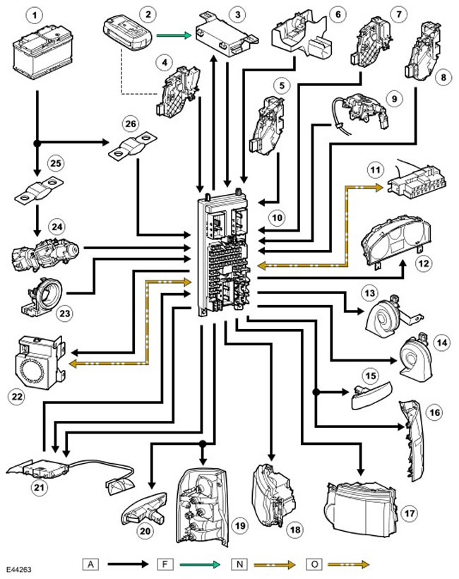
| Item name | Spare part catalog number | Description |
| 1 | - | Battery |
| 2 | - | Ignition key |
| 3 | - | Radio frequency receiver |
| 4 | - | Left front door open limit switch |
| 5 | - | Front right door open limit switch |
| 6 | - | Bonnet not closing limit switch |
| 7 | - | Left rear door open limit switch |
| 8 | - | Open right rear door limit switch |
| 9 | - | Open tailgate limit switch |
| 10 | - | CJB () |
| 11 | - | Diagnostic connector |
| 12 | - | Anti-theft alarm system |
| 13 | - | Left car horn |
| 14 | - | Right car horn |
| 15 | - | Right turn signal repeater |
| 16 | - | Right rear turn signal |
| 17 | - | Right front turn signal |
| 18 | - | Left front turn signal |
| 19 | - | Left rear turn signal |
| 20 | - | Left turn signal repeater |
| 21 | - | Penetration sensor |
| 22 | - | BBUS |
| 23 | - | Repeater coil |
| 24 | - | Ignition switch |
| 25 | - | Fuse link 11E in BJB block (battery switch unit) |
| 26 | - | Fuse link 17E in BJB block (battery junction box) |
Comments on this article