General information about the global positioning system (GPS)
A system designed to determine the current location of a vehicle is called a GPS system (global positioning system). The system uses Earth satellites owned by the US Department of Defense. 24 satellites with a period of revolution around the earth every 12 hours are located in orbits at an altitude of 20,000 km, and at any time in the field of view are from 5 to 11 satellites. The orbits are inclined to the Earth's equatorial plane by 55°to provide coverage of the polar regions. Each satellite sends out radio signals that completely determine the satellite's coordinates: longitude, latitude, altitude, as well as the date and exact time of day, which is generated by the onboard atomic clock. The number of atomic clocks on each satellite is four.
To accurately determine the three coordinates of the current position in space, the car must receive signals from at least four satellites.
If the vehicle is in motion, the specified information changes continuously. The navigation system computer determines which satellites are in view and calculates their relative position. Using this information, the computer compensates for deviations in the position of the satellites, which improves the accuracy of the vehicle's positioning.
Signals used by the GPS system (global positioning system), are called precise positioning signals (Precision positioning signal - PPS).
The predicted PPS accuracy is:
- 22 meters horizontally
- 27.7 meters vertically
- The time determination error is 200 nanoseconds.
The system uses reference data to determine the position of the vehicle. Reference data refers to data on the current status of 24 satellites orbiting the Earth.
The navigation system computer determines which satellites are in view and calculates their relative position. Using this information, the computer compensates for deviations in the position of the satellites, which improves the accuracy of the vehicle's positioning. To accurately calculate the three coordinates of the current position in space, the navigation system must receive reference data from at least four satellites. As the car moves, the computer constantly updates this information, so the computer has the exact position of the car in space at any given time.
Location of navigation system components
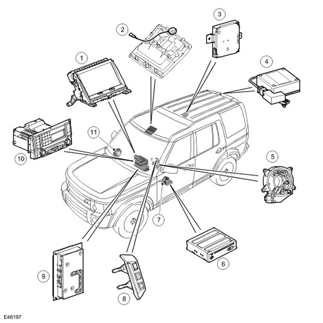
| Item name | Spare part number | Description |
| 1 | - | Touchscreen (TSD) |
| 2 | - | Microphone |
| 3 | - | Traffic message receiver (TMC) (if available) |
| 4 | - | GPS antenna (global positioning system) |
| 5 | - | Movable contact group |
| 6 | - | Navigation system computer |
| 7 | - | speaker |
| 8 | - | Steering wheel controls |
| 9 | - | Audio amplifier |
| 10 | - | Unified audio headunit (IHU) |
| 11 | - | speaker |
Navigation system control scheme
NOTE: A = wired connection D = CAN (local area network of controllers) P = MOST Q = GVIF
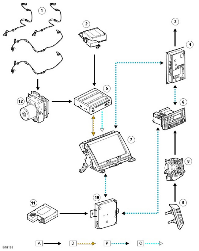
| Item name | Spare part number | Description |
| 1 | - | Wheel speed sensors |
| 2 | - | GPS antenna (global positioning system) |
| 3 | - | Speakers |
| 4 | - | Audio amplifier |
| 5 | - | Navigation system computer |
| 6 | - | Unified audio headunit (IHU) |
| 7 | - | Touchscreen (TSD) |
| 8 | - | Movable contact group |
| 9 | - | Steering wheel controls |
| 10 | - | Traffic message receiver (TMC) (if available) |
| 11 | - | Antenna amplifier for traffic message receiver (TMC) |
| 12 | - | ABS module (anti-lock braking system) |
Location of navigation system components with VICS (Japan only)
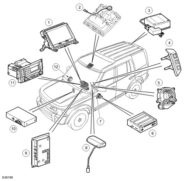
| Item name | Spare part number | Description |
| 1 | - | Touchscreen (TSD) |
| 2 | - | Microphone |
| 3 | - | GPS antenna (global positioning system) |
| 4 | - | Steering wheel controls |
| 5 | - | Movable contact group |
| 6 | - | Navigation system computer |
| 7 | - | speaker |
| 8 | - | VICS antenna |
| 9 | - | Audio amplifier |
| 10 | - | VICS receiver |
| 11 | - | Unified audio headunit (IHU) |
| 12 | - | speaker |
Navigation system control scheme with VICS (Japan only)
NOTE: A = wired connection; D = CAN (); P = MOST; Q = GVIF;
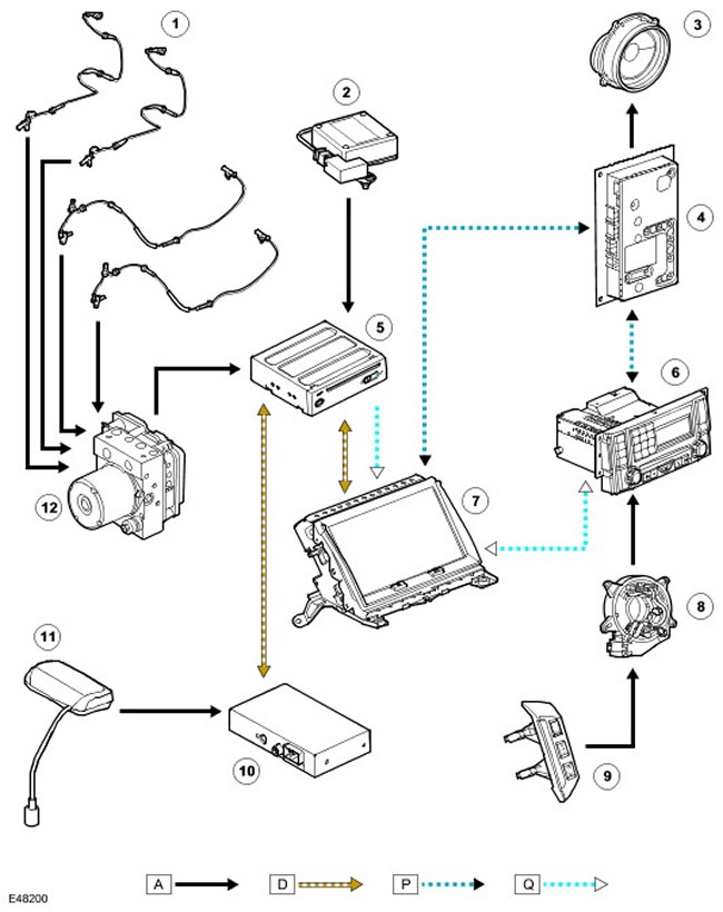
| Item name | Spare part number | Description |
| 1 | - | Wheel speed sensors |
| 2 | - | GPS antenna (global positioning system) |
| 3 | - | Speakers |
| 4 | - | Audio amplifier |
| 5 | - | Navigation system computer |
| 6 | - | Unified audio headunit (IHU) |
| 7 | - | Touchscreen (TSD) |
| 8 | - | Movable contact group |
| 9 | - | Steering wheel controls |
| 10 | - | VICS receiver |
| 11 | - | VICS antenna |
| 12 | - | ABS module (anti-lock braking system) |
The navigation system includes the following components:
- Touchscreen (TSD)
- Navigation system computer
- GPS antenna (global positioning system)
- Road services messaging channel (TMC)
- System for receiving messages from infrared and radio transmitters installed along the road (VICS, Japan only)
Touchscreen
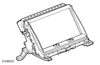
Touchscreen (TSD) located in the middle of the control panel. The TSD display is a 800 x 480 VGA LCD touch screen with a 15:9 aspect ratio. The TSD is connected to the MOST infotainment system. The MOST system is a fiber-optic data bus that provides high-speed transmission of control commands and audio signals in the system. For more information refer to Communications Network (418-00 Module Communications Network). For more information refer to Audio System (415-01 Audio Unit). For more information refer to Video System (415-07 Video System)
TSD performs independent processing of its video signals, however, all graphical navigation information comes from the navigation computer via a dedicated GVIF bus (Gigabit Video Interface). For more information refer to Communications Network (418-00 Module Communications Network)
Connector pins C2819
| contact no | Description | Input signal / output signal |
| 1 | Battery voltage | Input signal |
| 2 | Weight | - |
| 3 | Weight | - |
| 6 | Audio Screen Mode | - |
| 7 | (-) sound signal | - |
| 11 | ACC (auxiliary equipment) | Input signal |
| 12 | Dimming signal | Input signal |
| 14 | Dedicated CAN bus () (high level) | - |
| 15 | Dedicated CAN bus () (low level) | - |
| 17 | (+) sound signal | Input signal |
Connector pins C2820
| contact no | Description | Input signal / output signal |
| 1 | Video screen mode | - |
Connector pins C2823
| contact no | Description | Input signal / output signal |
| 1 | (+) GVIF | Input signal |
| 2 | (-) GVIF | - |
| 3 | GVIF bus shielding | - |
Connector pins C2825
| contact no | Description | Input signal / output signal |
| 1 | MOST input connector | Input signal |
| 2 | MOST output connector | Output signal |
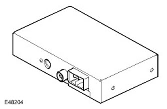
Navigation system computer
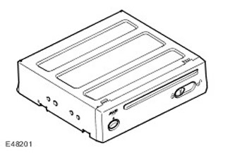
The navigation computer is located under the left front seat. The computer is the main device in the navigation system and receives input signals from the ABS unit (anti-lock braking system) and GPS antennas (global positioning system). The navigation computer contains a semiconductor piezoelectric gyro sensor that measures the movement of the vehicle along the vertical axis. The gyro sensor works on the principle of the Coriolis force. The Coriolis force is the force that arises to accelerate bodies moving from an axis of rotation in the direction of rotation of the axis. Using signals from the ABS unit (anti-lock braking system), GPS antennas (global positioning system) and a gyro sensor, the computer calculates the current position, direction and speed of the vehicle.
Your navigation computer also has a DVD drive ( (universal digital disc)) -ROM ( (in permanent storage)) . Drive used to read map data from DVD ( (universal digital disc)) - a disc designed for a specific region (1 DVD ((universal digital disc)) for each of the following regions: EU, US, Japan and Australia). Button located next to the DVD slot ( (universal digital disc)), used to upload DVD ( (universal digital disc)) from the device. If the ignition is on or the infotainment system is in one hour mode, the DVD ( (universal digital disc)) - The disc is ejected when the button is pressed once.
GPS receiver (global positioning system) receives information from one to eight satellites at a given time. This information is received by the GPS antenna (global positioning system). Built-in GPS receiver (global positioning system) used to calculate the position (those. longitude, latitude and altitude), direction and speed of movement.
The navigation computer uses non-volatile memory to retain settings and configuration data when the system is turned off. Memorization is carried out immediately before switching off.
IMPORTANT: If the device is turned off before the infotainment system is turned off, saving data to the computer will fail. This means that personal settings may be lost.
For the Japanese market, the navigation computer is a slightly different device. Despite the identical appearance, the software is adapted exclusively for Japan, and part numbers are also separated. The system also uses additional devices for the VICS system (receiver and antenna). VICS is equipped with receivers that allow the vehicle to receive traffic information from transmitters along the road and change the guidance of the navigation system accordingly. VICS information is received both by radio and by means of an infrared connection. For this reason, the antenna is located on the inside of the windshield.
Navigation computer connected to touch screen (TSD) via dedicated CAN bus () , as well as a separate line of a gigabyte video interface (GVIF). All video information is transmitted via the GVIF bus to the TSD, and via the CAN bus () commands and data are transferred to and from the TSD.
Connector pins C2114
| contact no | Description | Input signal / output signal |
| 3 | Weight | - |
| 6 | Dedicated CAN bus () (low level) | Input signal / output signal |
| 8 | Receiver VICS H-GND (weight) | Input signal |
| 9 | Receiver VICS H-TX- | Input signal |
| 14 | Mass of sound signals of voice control and navigation system | - |
| 15 | Microphone shielding weight | - |
| 16 | (-) voice recognition microphone | - |
| 17 | Battery voltage 12V (fuse 49) | Input signal |
| 18 | 12V battery power supply from infotainment system relay | Input signal |
| 19 | Weight | - |
| 21 | Vehicle speed signal from ABS control module (anti-lock braking system) | Input signal |
| 22 | Dedicated CAN bus () (high level) | Input signal / output signal |
| 30 | (+) audio signals voice control and navigation system | Output signal |
| 31 | Shielding/mass of audio signals of voice control and navigation system | - |
| 32 | (+) voice recognition microphone | Input signal |
Connector pins C2113
| contact no | Description | Input signal / output signal |
| 1 | (+) GVIF | Output signal |
| 2 | (-) GVIF | - |
| 3 | GVIF weight | - |
Connector pins C1599
| contact no | Description | Input signal / output signal |
| 1 | GPS Antenna Shield Weight (global positioning system) | Output signal |
| 2 | GPS antenna signal (global positioning system) | Input signal |
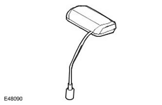
GPS antenna
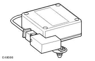
GPS antenna (global positioning system) located in the rear spoiler. GPS antenna (global positioning system) connected to a GPS computer (global positioning system) one coaxial cable, receives signals from GPS satellites (global positioning system) and transmits them to the receiver built into the computer.
There is a possibility that the GPS antenna (global positioning system) may lose GPS signal (global positioning system) from GPS satellites (global positioning system) in mountainous or densely forested areas, in places with tall buildings, in multi-storey car parks, garages, tunnels, bridges, or during heavy rain/thunderstorms. In this case, the navigation system continues to operate until communication is restored, based only on the information recorded on the DVD ( (universal digital disc)).
Traffic Channel Receiver (TMC)
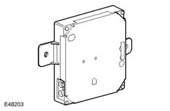
The TMC receiver is located in the rear RH (right) parts of the luggage compartment. The receiver is connected to the MOST network and transmits traffic information to the navigation computer via TSD. The navigation computer then displays this information and changes the recommended route to avoid traffic areas. TMC data is received by the FM antenna integrated in the tailgate window via an antenna amplifier located above the tailgate spoiler. For more information refer to Antenna (415-02 Antenna)
The TMC function is provided in models supplied to the markets of many European countries.
VICS receiver for receiving messages from infrared and radio transmitters installed along the road (Japan only)
The VICS system includes the following elements:
- VICS receiver
- Infrared Antenna VICS
- VICS radio antenna
VICS receiver located behind integrated audio headunit (IHU) in the instrument panel. The VICS receiver is connected to the navigation computer via a dedicated line.
The VICS receiver receives information from an antenna located in the center of the control panel and from an antenna built into the rear window. For more information refer to Antenna (415-02 Antenna)
Infrared Antenna VICS
The infrared VICS antenna is mounted on top of the control panel. The antenna receives signals in the infrared and radio frequency ranges from transmitters installed along the road.
Operation of the navigation system
The navigation system receives GPS information (global positioning system) from satellites via GPS antenna (global positioning system). Based on GPS signals (global positioning system), received from satellites, the navigation system computer calculates the position of the vehicle. After the driver enters the desired destination, the navigation system computer calculates the route based on the preferences preset by the driver or on the settings «default», embedded in the computer.
The navigation system is activated by a button located in the lower left corner of the touch screen. The driver can select either on-road or off-road navigation mode.
Road navigation
This navigation mode is activated after the driver indicates a destination. This can be done in the following ways:
- By entering data manually or by selecting an address on the TSD screen.
- Postcode entry.
- Select a destination previously entered in the address book.
- Selecting a destination in the displayed area.
Off-road navigation
This navigation mode indicates a sequence of points in the terrain, which must be passed one after the other. First, the system guides you step by step to the first waypoint. When the vehicle arrives at the first waypoint, the system guides the driver to the second waypoint. This process continues until the car arrives at its destination.
The routes are stored in the non-volatile memory of the navigation computer.
Routes can be displayed on the touch screen with via points, latitude and longitude of the destination, as well as previously saved routes.
Various display formats provide the driver with the information required for direct turn-by-turn driving to the destination (route guidance mode). The same screen formats are available in the absence of recommendations (compass driving mode). However, in this case, no route guidance information is displayed. When the system is in compass driving mode, when route guidance information is not displayed, the message "COMPASS MODE" (compass driving mode).
4x4 l
The 4x4 l system gives the driver additional information about the vehicle's systems.
- suspension travel
- Selected Gear
- Selected Range
- Type of road surface
- Vehicle heading
- Azimuth
- Steering angle
Road services messaging channel (TMC)
Road services messaging channel (TMC) are one of the FM functions (radio data transmission system) broadcasting in the RDS band (frequency modulation). The system transmits real-time traffic and weather reports. The data is received and decoded by the TMC receiver and sent to the navigation system, which forwards it on its interface. TMC messages are filtered in the navigation computer so that only messages relevant to the trip are displayed. This allows the navigation system to correct the route in time and offer the driver an alternative route to avoid accidents.
The traffic messaging system complies with global standards approved by traffic information organizations, information service providers, radio stations, and car radio manufacturers. TMC information is received using a conventional FM antenna.
All TMC radios use the same list of event codes, but local databases (on the roadmap disc) may additionally contain country-specific codes for strategic European roads.
Currently, TMC information is broadcast in most European countries.
Automotive information and communication system VICS (Japan only)
The VICS system provides information to the navigation system computer that can be used to change the recommended route or warn the driver of a traffic situation in the vicinity of the vehicle's location. Information enters the system through three channels:
- radio frequency channel;
- infrared channel;
- FM multi-channel transmission channel.
RF transmission
Radio frequency transmission is usually carried out from transmitters («radio beacons»), installed along roads, mainly on high-speed highways. The following information is transmitted:
- traffic density
- Driving time to the next intersection
- Road conditions in neighboring areas and the possibility of exiting the motorway
- traffic accidents
- Speed Limit
- Lane change rules
- Rules for driving within a row
- Permissibility of parking and availability of parking areas on highways
Infrared transmission
Infra-red broadcasts are broadcast by radio beacons installed along the main roads. The following information is transmitted:
- Traffic density and driving time
- traffic accidents
- accidents
- Lane restrictions due to renovations
- Parking availability
FM data transmission
The FM data transmission is broadcast as part of the normal RDS FM data transmission (radio data transmission system). The following information is transmitted:
- Traffic density and driving time (covers a large area)
- Traffic Accidents, Repairs, Speed Limits and Lane Change Rules (covers a large area)
- Information about parking availability.
Diagnostics
The touch screen and navigation computer perform self-diagnosis, allowing the mechanic to troubleshoot the system. Diagnostic codes can be read using the T4 tool.
TSD Display Diagnostics
Built-in diagnostic functions allow you to identify errors in the operation of the touch display. The mechanic can test the system for the following items:
- Operation of hardware keys
- Touch screen functions
- Video input
- Image RGB
- Video signals
- Self-diagnosis
- system configuration
- Vehicle configuration
- MOST bus operation
- After turning on the system, enter the main menu.
- Press the top center of the screen for approximately 5 seconds and then press the navigation system hard key.
- The Diag PIN Entry window will be displayed, enter the passcode 753.
- As soon as the system accepts the code, the diagnostic menu will appear on the screen.
Checking Display Hardware Keys
Testing is carried out to verify the functioning of the two hardware keys built into the touch display. If the key is working, when you press the corresponding icon on the screen, the latter will be displayed on a green background.
Touch screen test
By entering the touch screen test mode, the mechanic can test the reaction of the screen when touched. He can either check that the screen is working or recalibrate it. After pressing the key «Touch Check Switch» (Checking touch switches) the screen will be blank. When you touch the screen anywhere, the coordinates of the corresponding point are displayed. If you touch the faulty area of the screen, the coordinates will not be displayed.
Calibrating the screen will ensure that the coordinates of the touch points match. To do this, click on the various «targeted» screen dots.
Signals from vehicle systems
The vehicle signal window on the TSD displays input signals from other vehicle systems. Among them:
- Battery voltage
- Lighting (on or off)
- Ambient light sensor voltage
- Decreasing the brightness of instrument lighting
- Audio Output Distribution
- PCB block temperature
- speed limit (on or off)
- MOST bus FOT temperature
- Parking position (electric parking brake on or off)
- PWM signal duty cycle (pulse width modulation) screen backlight
- Beep volume
- Sound tone
Checking video inputs
With this function, you can test the video inputs of the touch display. These include TV/DVD inputs ( (universal digital disc)) (TV, connection with DVD player) infotainment system for rear passengers (RSE).
Checking RGB colors
This feature allows the mechanic to check the colors generated by the touch screen. Six monochrome colors are displayed on the screen. Selecting any of them results in a solid fill of the screen with the selected color. Touching the screen again returns it to color selection mode.
Self-diagnosis
The self-diagnostic function displays the current trouble codes of the touch display. In addition, the status of the ignition switch and battery voltage are displayed.
Two additional softkeys allow you to clear trouble codes and check the TSD.
System configuration
Information about the touch screen and the navigation computer is displayed on the screen. Switching between the two specified components is done using the soft key in the upper LH (left) corner of the screen.
The following information is available:
- car type
- component serial number
- part number
- component group number
- main processor bootloader version
- computer main software version
- version of additional computer software
- dedicated CAN bus database version ()
Vehicle configuration
Selecting an option «Vehicle configuration» allows the mechanic to check which infotainment system components are installed on the vehicle. This option is located on four screens, the transition between which is carried out by the keys «Forward» And «Back».
MOST bus test
The MOST bus test screen displays information about the signals transmitted on this stub bus. When using any part of the audio system, a message is displayed on the screen, transmitted via the MOST bus. This allows you to identify faults associated with this data bus.
Navigation computer diagnostics
Built-in diagnostic functions allow you to identify errors in the operation of the navigation computer. The mechanic can test the system for the following items:
- navigation system information
- information about system components
- manual check
- self-diagnosis
- After turning on the system, enter the menu of the navigation system by pressing the hardware button of the navigation system.
- Agree to cancel the screen.
- Enter the main menu of the navigation system.
- Long press on the top center of the touch screen.
- The Diag PIN Entry window will be displayed, enter the passcode 753.
- navigation system information
- manual check
- information about system components
- Self-diagnosis
Navigation information
This menu item has three subsections:
- Video signals
- GPS Information (global positioning system)
- Reset position
Information about system components
If you select this option, the system will provide information about components and software versions.
Manual check
The menu provides the ability to perform the following tests:
- Checking the RGB colors of the navigation system screen.
- Checking the level at the microphone input.
- Checking the output signals of the voice messaging system.
Self-diagnosis
The self-diagnosis consists of an internal check of the navigation system computer's health by displaying fault codes on the touch screen.
DTC (diagnostic trouble code) navigation system
| Output DTC (diagnostic trouble code) | DescriptionDTC (diagnostic trouble code) | Possible cause of malfunction |
| U1A0087 | Dedicated CAN bus failure () | Disconnecting the connector from the navigation computer. Communication error. |
| B1B0049 | Navigation computer internal error | |
| B1A0049 | Internal TSD fault | |
| B1A8911 | GPS antenna short circuit (global positioning system) to ground | GPS communication error (global positioning system) |
| B1A8913 | An open in the GPS antenna circuit (global positioning system) | GPS communication error (global positioning system) |
| B1D6287 | Communication error with VICS controller | |
| B1D6249 | VICS controller error | |
| U1A0131 | GVIF error | No connection to GVIF |
| U300068 | FOT MOST overheating | Overheating of the MOST transceiver |
| B100E25 | TV/RSE video input failure | No input connection |
| B100F25 | Merged camera video input failure | No input connection |
| B101025 | Rear camera video failure | No input connection |
| U200531 | Vehicle speed signal malfunction | Mismatch between vehicle speed and GPS data (global positioning system) |
Comments on this article