Contents: Description of the master cylinder ⇩ Master Cylinder Elements ⇩ Master cylinder operation ⇩ Master cylinder repair parts ⇩ Hydraulic system ⇩ Models 90 ⇩ Models 110/130 ⇩ Front brake caliper assembly ⇩ Rear brake caliper assembly ⇩ Standing night brake ⇩
Description of the master cylinder
The mechanical elements of the hydraulic brake system consist of brake discs with four-piston calipers at the front and brake discs with two-piston calipers at the rear.
Front ventilated discs are standard on the 110/130 models, while the 90 models have non-ventilated discs. However, front ventilated discs are also available on the 90 models with heavy-duty chassis.
The cable-operated parking brake operates a single drum brake mounted on the output shaft of the transfer case and is completely independent of the main braking system.
The main hydraulic system includes 2 separate and independent circuits - primary and secondary, which allow you to adjust the degree of braking in the event of a malfunction in one of the circuits. The primary circuit controls the rear brake calipers, and the secondary circuit - the front brake calipers.
Master Cylinder Elements
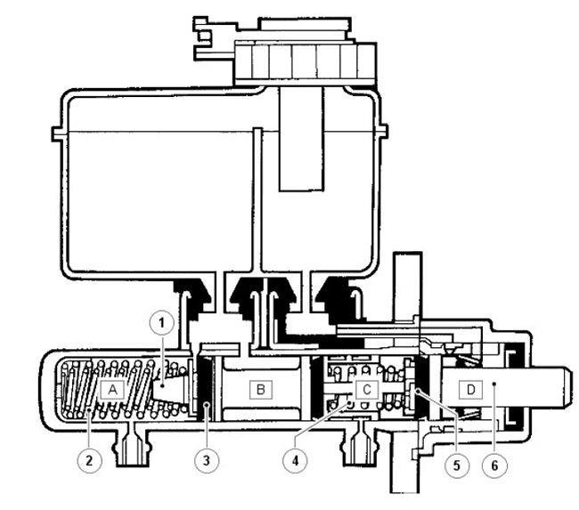
| Pos. | Spare part number | Name |
| 1 | - | Auxiliary piston |
| 2 | - | Secondary spring |
| 3 | - | Primary cuff |
| 4 | - | Primary spring |
| 5 | - | Primary cuff |
| 6 | - | Main piston |
Master cylinder operation
The tandem master cylinder, assisted by a light, short and compact servo cylinder, is fed from a separate reservoir. The rear section supplies brake fluid to the primary circuit, and the front section to the secondary circuit.
When the brakes are not applied, brake fluid can move freely through the dual circuit system and between the separate tanks of the brake fluid supply reservoir.
When the brake pedal is pressed, the primary piston rises in the cylinder, the resulting pressure in combination with the primary spring overcomes the force of the secondary spring, thus raising the secondary piston in the cylinder. At the same time, the initial movement of both pistons moves the primary seal so that it closes the cut-off holes in the cylinder chambers "A" and "C", see J6321; the brake fluid in these chambers is subjected to pressure and is directed into the appropriate circuits.
The movement of the pistons does not affect the brake fluid in chambers "B" and "D"; the fluid can move freely between the individual chambers and the corresponding tanks of the supply reservoir, both before the brake pedal is pressed and after the brakes are applied. When the brakes are released, the pistons, with the help of return springs, move back faster than the brake fluid; this creates a pressure difference between the brake fluid in chambers "A" and "C" and the primary cuffs.
The primary seals instantly contract, allowing the brake fluid in chambers "B" and "D" to flow through the holes in the pistons, through the contracted seals into chambers "A" and "C" respectively. The movement of brake fluid from one set of chambers to another is compensated by brake fluid from separate tanks in the feed reservoir, which passes through the feed holes in the cylinder. The final return movement of the pistons causes excess brake fluid in chambers "A" and "C" to flow through the cut-off holes into the brake fluid feed reservoir.
The servo unit facilitates pressing the brake pedal by providing an auxiliary force. The auxiliary force is provided by a vacuum pump located on the right side of the cylinder block. A vacuum is created on both sides of the flexible diaphragm; atmospheric pressure acts on the rear diaphragm, thereby achieving an auxiliary force. The servo unit is installed between the brake pedal and the master cylinder and is connected to them by push rods. If the vacuum is broken, the two push rods begin to act as a single unit, thereby ensuring normal functioning of the brakes. But in this case, more force is required to operate the brake pedal.
Master cylinder repair parts
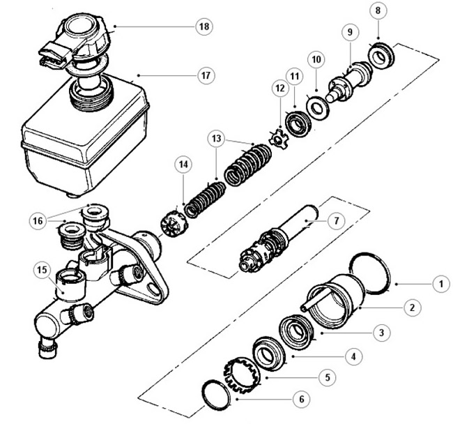
| Pos. | Spare part number | Name |
| 1 | - | Sealant that protects against water penetration |
| 2 | - | Transfer case |
| 3 | - | Vacuum sealer |
| 4 | - | Guide ring |
| 5 | - | Retaining ring |
| 6 | - | O-ring with circular cross section |
| 7 | - | Main piston assembly |
| 8 | - | L-shaped seal |
| 9 | - | Auxiliary piston |
| 10 | - | Washer |
| 11 | - | Primary cuff |
| 12 | - | Seal housing |
| 13 | - | Springs |
| 14 | - | Spiral pipeline |
| 15 | - | Master cylinder housing |
| 16 | - | Tank seals |
| 17 | - | Tank |
| 18 | - | Low Brake Fluid Switch and Cap |
Hydraulic system
At the recommended service intervals, it is necessary to drain the brake fluid and flush the brake system.
The brake fluid loss sensor is mounted on the filler cap of the master cylinder reservoir. The sensor is connected to the control lamp circuit on the vehicle's instrument cluster; the lamp comes on during the indicator lamp check when the ignition is turned on and goes out when the engine is started and the parking brake is released. A hydraulic fault in the system will cause a loss of brake fluid, causing the indicator lamp to come on.
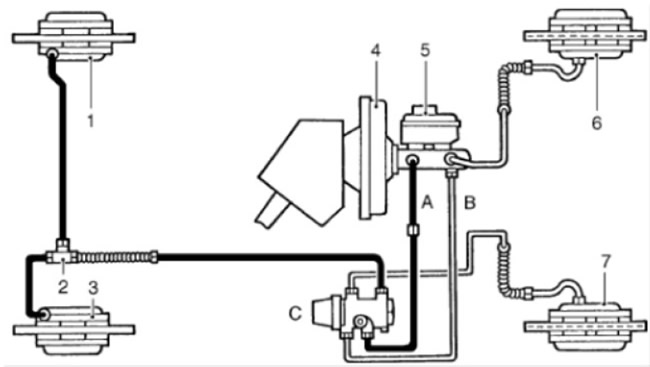
On 90 models, a pressure reducing valve (PRV) mounted on the right-hand bulkhead in the engine compartment maintains brake balance, see J6322. The pressure supplied to the rear brake calipers is controlled by the PRV. This valve is a type of emergency bypass valve; in case of front failure (secondary) brake circuit, it directs all the pressure in the system to the rear brake calipers.
Models 90
Models 110/130
NOTE: In some countries, to comply with legal requirements, a pressure reducing valve may be fitted to the 110 model.
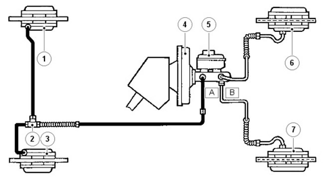
| Pos. | Spare part number | Name |
| A | - | Main circuit |
| B | - | Secondary circuit |
| C | - | Pressure reducing valve |
| 1 | - | Left rear brake caliper |
| 2 | - | Tee |
| 3 | - | Right rear brake caliper |
| 4 | - | Brake servo cylinder |
| 5 | - | Master cylinder and reservoir |
| 6 | - | Left front brake caliper |
| 7 | - | Right front brake caliper |
Front brake caliper assembly
Front brake caliper components
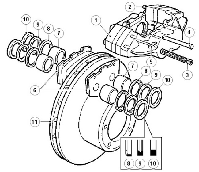
| Pos. | Spare part number | Name |
| 1 | - | Support |
| 2 | - | Air release screw |
| 3 | - | Anti-rattle springs |
| 4 | - | Shoe mounting pins |
| 5 | - | Cotter pin |
| 6 | - | Friction linings |
| 7 | - | Piston |
| 8 | - | Mud seal retainer |
| 9 | - | Wiper cuff |
| 10 | - | Hydraulic seal |
| 11 | - | Brake disc |
Rear brake caliper assembly
Rear brake caliper components
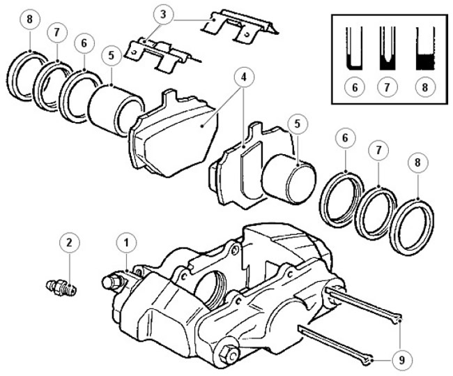
| Pos. | Spare part number | Name |
| 1 | - | Support |
| 2 | - | Air release screw |
| 3 | - | Locking springs of the lining |
| 4 | - | Brake pads |
| 5 | - | Piston |
| 6 | - | Wiper Seal Retainer |
| 7 | - | Wiper cuff |
| 8 | - | Hydraulic seal |
| 9 | - | Mounting pins |
Rear Brake Caliper Installation - 2002 Model Year Onwards
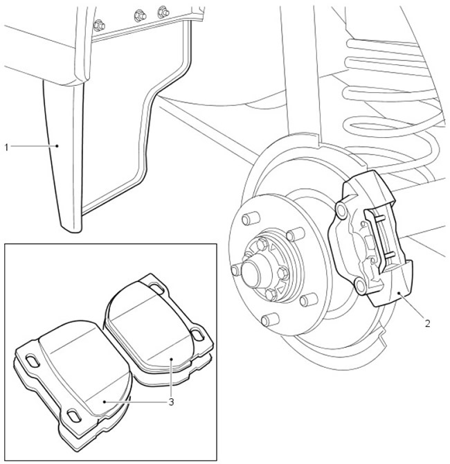
[The original was published on the portal LRman.ru]
| Pos. | Spare part number | Name |
| 1 | - | Deflector |
| 2 | - | Rear brake caliper |
| 3 | - | rear brake pads |
Modifications to the rear brakes were introduced on the 110 and 130 models. This is necessary to increase the service life of the rear brake pads in harsh external conditions.
New rear brake calipers are introduced, allowing the use of brake pads with a thicker layer of friction material. The brake pads have increased chamfers at the front and rear edges, which improves efficiency.
Aerodynamic deflectors are located in front of the rear wheels to protect the rear calipers from dirt that could cause excessive pad wear. The deflectors are fitted to 90, 110 and 130 models sold in countries where environmental conditions could cause excessive brake pad wear.
Standing night brake
Parking brake components
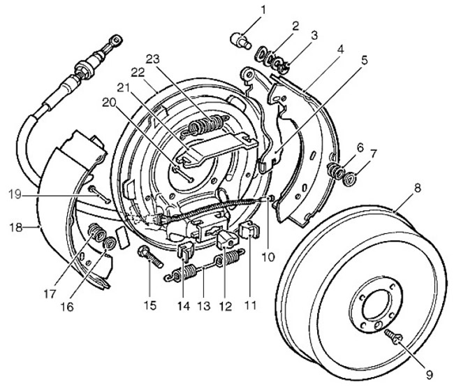
| Pos. | Spare part number | Name |
| 1 | - | Pin |
| 2 | - | Washer |
| 3 | - | C-clamp |
| 4 | - | Brake shoe |
| 5 | - | Cable lever |
| 6 | - | Retaining spring |
| 7 | - | Plate washer |
| 8 | - | Brake drum |
| 9 | - | Screw |
| 10 | - | Brake cable |
| 11 | - | Regulator slider |
| 12 | - | Regulator nut |
| 13 | - | Spring |
| 14 | - | Regulator slider |
| 15 | - | Adjusting bolt |
| 16 | - | Plate washer |
| 17 | - | Retaining spring |
| 18 | - | Brake shoe |
| 19 | - | Support stand |
| 20 | - | Support stand |
| 21 | - | Support plate |
| 22 | - | Brake shield |
| 23 | - | Spring |
Comments on this article