Disassembly
1. Disconnect the battery and remove the master cylinder from the booster.
For more information, refer to the chapter: Disconnecting and connecting the battery (414-01 Battery, Battery Mounting and Cables, General Procedures).
2. Before starting a major overhaul, thoroughly clean the master cylinder and inspect the outer surfaces for damage and check the general condition. If necessary, replace the entire unit.
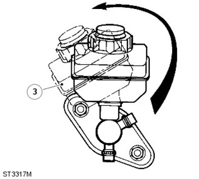
3. The reservoir is installed with a tight fit on the master cylinder and is fixed with seals. Carefully remove the reservoir from the master cylinder by "unscrewing" it from the seals, as shown in the figure.
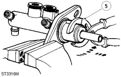
4. Clamp one side of the master cylinder flange in a vice with soft jaws. Remove the O-ring from the flange between the master cylinder and booster and discard it.
5. Grasp the outside of the coupling housing with suitable pliers and gently pull the housing out while using a rocking motion with the pliers back and forth to disengage the housing from the master cylinder. Discard the housing and vacuum seal.
6. Remove the two reservoir seals from the master cylinder and mark their positions in the intake ports for reassembly purposes. Discard both seals.
7. Remove the retaining ring and O-ring from the machined outside surface of the master cylinder. Discard the seal and retaining ring.
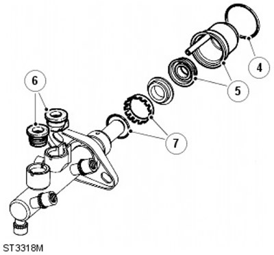
8. Remove the guide ring from the master cylinder port that supports the primary plunger assembly and set it aside. This item is not included in the master cylinder service kit and must be replaced when reassembling the unit.
9. Remove the primary plunger assembly from the master cylinder.
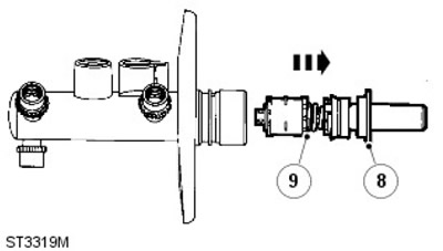
NOTE: The primary plunger assembly cannot be disassembled further and is serviced as a single unit. Discard the unit.
10. The secondary plunger assembly will remain in the bottom of the master cylinder bore. The plunger can be easily removed by tapping the cylinder with a piece of wood until the plunger appears in the cylinder port. Then carefully remove the plunger from the master cylinder.
11. If the swirl tube was not removed at the same time as the secondary plunger, repeat the above steps to remove it from the bottom of the master cylinder bore. Then discard it.
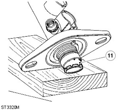
12. Clean all components with Gilling cleaning fluid or fresh brake fluid. Place the cleaned components on a clean sheet of paper. Inspect the cylinder bore and plungers for signs of corrosion, wear ridges and scratches. If the working surfaces are in excellent condition, new seals from the Gilling service repair kit can be used.
13. Remove the above components from the secondary plunger and discard them:
| Pos. | Name |
| A | Springs |
| B | Seal stop |
| C | Front cuff |
| D | Washer |
| E | L-shaped seal |
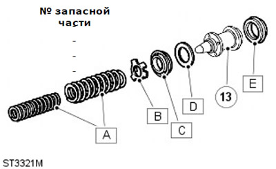
NOTE: A small screwdriver with a rounded and polished end is required to remove the L-ring seal. DO NOT damage the secondary plunger.
14. Wet the new seals with fresh brake fluid and install the L-shaped seal onto the plunger first.
15. Install the washer, followed by the front seal. Install the seal retainer and springs, making sure that the springs are installed correctly.
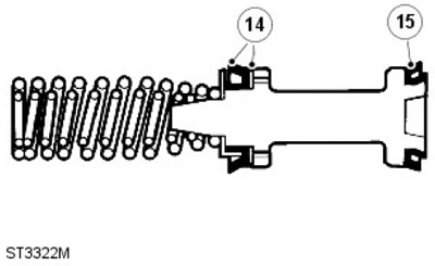
CAUTION: Be sure to follow the instructions exactly. Otherwise, when installing the plungers into the cylinder bore, the new seals may be damaged. Before assembly, lubricate the components generously with new brake fluid.
NOTE: Be careful to ensure that no dirt gets into the passages and holes. If dirt is found, carefully remove it, clean the cylinder again and recheck.
1. Install a new swirl tube into the bottom of the cylinder bore.
2. Lubricate the secondary plunger and the cylinder bore. Insert the plunger assembly into the cylinder until the seal is centered against the bell of the bore. Gently insert the plunger using a rocking motion as shown. Make sure the seal does not stick, insert the seal into the bore and slowly push the plunger into the bore in one continuous motion.
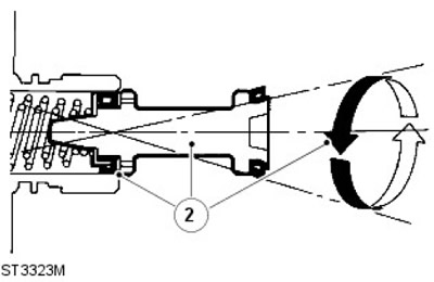
3. Install the primary plunger assembly using the same method as the secondary plunger. Press the plunger into the bore.
4. Install the original guide ring to support the primary plunger.
5. Apply brake fluid to the new O-ring and insert it into the corresponding groove on the outer mounting surface of the master cylinder.
CAUTION: The seal ring should not be twisted on the outer mounting surface of the master cylinder, but should be slightly stretched and lowered into the cylinder and its groove. Do not stretch the seal too much.
6. Install the new mounting ring onto the outside surface of the master cylinder, ensuring that the small teeth of the ring face the mounting flange.
7. Insert two new reservoir seals into the appropriate ports.
8. Install a new vacuum seal onto the primary plunger or into the bottom of the coupling housing bore, with the open side of the seal facing the primary plunger guide ring.
9. Lubricate the vacuum seal with brake fluid, install the coupling housing on the master cylinder, fully press the housing upward to the cylinder mounting flange. Do not adjust the position of the coupling housing after installation.
10. Lubricate the new water seal with brake fluid, stretch the seal slightly and push it down into the housing until the seal is in the correct position between the housing and the flange.
11. Install the reservoir on top of the master cylinder, working in the reverse order of the procedure described in point 3.
12. Install the master cylinder onto the booster.
For more information, refer to the chapter: Brake Master Cylinder (206-06 Hydraulic brake drive, Removal and installation).
13. Reconnect the battery and road test the vehicle.
Comments on this article