


Contents: Master cylinder ⇩ Tank ⇩
NOTE: Right hand drive version shown; the left-hand drive version has a similar design.
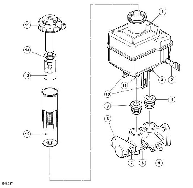
| Item name | Spare part catalog number | Description |
| 1 | - | Tank |
| 2 | - | Clutch Bleed Port Fitting and Seal Cap |
| 3 | - | Main outlet nipple |
| 4 | - | Seal of the main inlet port of the reservoir for connecting the master cylinder |
| 5 | - | Main outlet |
| 6 | - | Tank mounting pin |
| 7 | - | Auxiliary outlet |
| 8 | - | Cylinder body |
| 9 | - | Seal of auxiliary inlet port of reservoir for connection of master cylinder |
| 10 | - | Tank mounting straps |
| 11 | - | Auxiliary outlet nipple |
| 12 | - | Filter |
| 13 | - | Float |
| 14 | - | Magnet |
| 15 | - | Tank cap and liquid level sensor |
The master cylinder and reservoir are mounted to the front of the brake booster on the driver's side of the engine compartment.
Master cylinder
The master brake cylinder consists of a cylinder body and two twin pistons. The rear piston creates pressure in the main circuit, and the front piston creates pressure in the auxiliary circuit. The pistons have central valves with a large throughput, ensuring sufficient fluid supply to the hydraulic control unit to ensure stability.
When the brake pedal is pressed, the front piston rod of the brake booster moves the main piston along the hole in the cylinder body. This creates pressure in the main pressure chamber, which, together with the main spring, overcomes the resistance of the auxiliary spring and simultaneously moves the auxiliary piston in the hole. The initial movement of the pistons from the travel stops causes the main and auxiliary central valves to close. Further movement of the pistons creates fluid pressure in the main and auxiliary pressure chambers and, consequently, in the brake system circuits. The movement of the pistons does not affect the fluid in the chambers behind the pistons, and this fluid can flow without restrictions through the feed holes in the chambers and the reservoir.
When the brake pedal is released, the primary and secondary springs return the pistons to their lower positions inside the cylinder body. When the pistons reach the stroke stops, the main and secondary central valves open, allowing fluid to flow freely between the two hydraulic circuits and the reservoir, through the central valves, the chambers behind the pistons and the inlet ports in the cylinder body.
If one of the brake system circuits fails, the remaining brake system circuit remains effective, but the brake pedal travel and the vehicle's braking distance increase.
Tank
The reservoir is mounted on top of the master cylinder and supplies brake fluid to the main and auxiliary brake circuits. On manual transmission models, the reservoir also supplies brake fluid to the clutch. For more information, see Clutch Controls (308-02 Clutch Controls - 2.7L Diesel).
Two bands on the sides of the reservoir engage pins on the master cylinder to secure the reservoir in place. Two outlet fittings on the bottom of the reservoir fit into seals on the inlet ports of the master cylinder. The outlet fitting on the left side of the reservoir is for the hydraulic clutch circuit. (if available). On models with automatic transmission, the clutch outlet nipple is sealed with a sealing cap formed during manufacture of the reservoir. This cap is removed only when installing the reservoir on models with manual transmission.
The tank has internal partitions to separate the circuits when the liquid level is low, and to prevent leakage from one circuit if another circuit fails. The partitions support the central well and divide the space around it into eight sections. The well is an extension of the filler neck and contains a filter and a liquid level sensor.
The reservoir and its surrounding compartments are connected by slots in the partitions. The slots are arranged so that when the reservoir is full, fluid can flow between the reservoir and all of the surrounding chambers, but when the fluid level is low, the internal partitions form separate reservoirs for all of the circuits. The following figure shows the separate reservoirs for each circuit and the amount of brake fluid remaining in each reservoir in the event of a leak in one of the other circuits.
Comments on this article