NOTE: A = Clutch fluid reservoir; B = main circuit tank; C = auxiliary circuit tank.
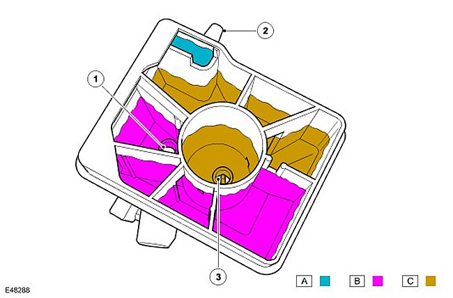
| Item name | Spare part catalog number | Description |
| 1 | - | Main outlet |
| 2 | - | Clutch release port |
| 3 | - | Auxiliary outlet |
The filler neck of the tank has a tightly closing lid with a level sensor. The level sensor is activated by a magnet, which is installed in the float on the bottom of the sensor. The sensor responds to changes in the magnetic field surrounding the magnet.
When the reservoir is full, the float rests against the bottom of the sensor and holds the sensor circuit open. As the fluid level drops, the float moves downward, causing the sensor to close, grounding the instrument cluster circuit. When the circuit is grounded, the instrument cluster lights a red LED in the brake warning lamp. On vehicles with a high-level instrument cluster, a warning is also displayed in the message center display. For more information, refer to Instrument Cluster (413-01 Instrument Cluster) At the beginning of each ignition cycle, the instrument cluster performs a test of the brake system status indicator LED.; the indicator lights up yellow for 1.5 seconds and then red for 1.5 seconds.
The instrument cluster transmits the brake fluid level status via the high-speed CAN bus to the anti-lock brake system (ABS) module. For more information, refer to AntiLock Control - Traction Control (206-09A Anti-Lock Control - Traction Control).
Details can be found on the website LRman.ru
Comments on this article