Contents: Internal support bracket ⇩ Fuel Delivery Module ⇩ Fuel level indicator sensors ⇩ Fuel tank breather valve ⇩
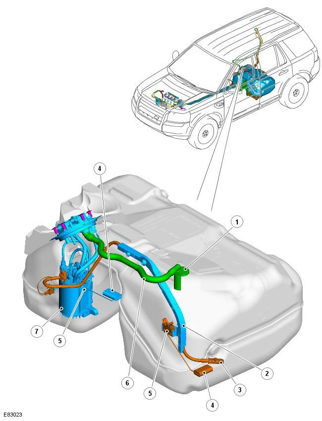
| Pos. | Spare part number | Name |
| 1 | - | Fuel tank vent valve |
| 2 | - | Cross pipeline |
| 3 | - | Coarse filter |
| 4 | - | Fuel level indicator sensor float (2 pcs.) |
| 5 | - | Fuel level indicator sensor type MAPPS (magnetic passive position sensor) (2 pcs.) |
| 6 | - | Fuel tank vent hose |
| 7 | - | Fuel Delivery Module |
The fuel tank consists of the following internal elements:
- Internal support bracket
- Fuel delivery module and cross-pipe
- Two MAPPS type fuel gauge sensors
- Breather
Internal support bracket
The internal support bracket is molded into the tank body and serves to accommodate the breather and cross pipe assembly.
Fuel Delivery Module
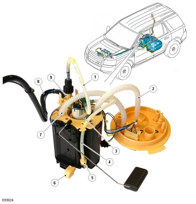
| Pos. | Spare part number | Name |
| 1 | - | Feed from a pump built into the tank to a transfer pump |
| 2 | - | Fuel supply to the engine fuel filter |
| 3 | - | Pump located in the fuel tank |
| 4 | - | Feed from a pump built into the tank to a transfer pump |
| 5 | - | Transfer pump (useful side of tank) |
| 6 | - | Inlet from the useful side of the tank |
| 7 | - | Returning fuel from the engine fuel filter |
| 8 | - | Cross pipe (from the useful side of the tank) |
| 9 | - | Transfer pump (unused side of tank) |
The fuel delivery module is located on the right side of the tank and is secured to the bottom of the tank with a welded bayonet-type retaining ring. The top flange of the fuel delivery module assembly provides the interface between the internal and external electrical and fuel connections of the tank. The flange has a 6-pin external electrical connector that is connected to two MAPPS fuel level sensors and an in-tank pump.
The fuel supply module flange is sealed against the tank with an O-ring and secured with a retaining ring.
The lower portion of the fuel delivery module forms the fuel delivery reservoir and serves to house the in-tank pump and two transfer pumps. The fuel delivery reservoir provides a permanent storage location for the fuel drawn into the engine. The engine's supply and return fuel lines are submerged in the fuel delivery reservoir.
The tank is kept full by two transfer pumps. A pump built into the tank takes fuel from the supply tank and "drives" it through the two transfer pumps. The flow of fuel through each transfer pump creates a suction effect that draws fuel from both sides of the fuel tank into the fuel supply tank. Excess fuel entering the fuel supply tank flows to the usable side of the fuel tank.
The valve is located in the lower (useful side of the tank) feed port of the transfer pump. The valve is open when the in-tank pump is activated and the lower transfer pump supplies fuel to the fuel supply tank. When the in-tank pump is deactivated, the valve closes to prevent fuel from draining from the fuel supply tank.
The in-tank pump is energized through the fuel pump relay located in the central junction box (CJB). The engine control module (ECM) energizes the fuel pump relay whenever the ignition is in power mode 4 (accessory power) or mode 9 (cranking). For additional information, refer to: Electronic Engine Controls - 2.2L Diesel (303-14 Electronic Engine Controls - 2.2L Diesel, Description and Operation).
The modified fuel delivery module, which is installed on vehicles operated in cold climates, includes a fuel-fired auxiliary heater and an auxiliary fuel pump. The modified fuel delivery module has a separate fuel supply line that is connected to the auxiliary fuel pump, which is mounted externally on the right side of the tank. The auxiliary fuel line connects the auxiliary fuel pump to the fuel-fired auxiliary heater. For additional information, refer to the chapter: Auxiliary Fuel Heater (412-02 Auxiliary Climate Control, Description and Operation).
Fuel level indicator sensors
Two MAPPS fuel level sensors are located on either side of the saddle-shaped tank and are connected to internal electrical connections on the fuel delivery module flange. Each sensor sends an electrical signal to the CJB that is proportional to the fuel level on that side of the tank.
The actual fuel level in the tank is calculated in the CJB and this information is transmitted via the medium speed CAN bus to the instrument cluster.
A warning light in the instrument cluster comes on when the amount of fuel in the tank drops to or below a preset level. On vehicles equipped with a "high series" instrument cluster, a message is displayed and a warning signal sounds to inform the driver that the fuel supply needs to be replenished.
For further information, refer to the chapter: Instrument cluster (413-01 Instrument cluster, Description and operating principle), Information and message centre (413-08 Information and message centre, Description and operating principle).
Fuel tank breather valve
The vent valve is located in the fuel tank and is connected to the fuel delivery module flange via an internal vent hose. The vent valve allows air to escape and then enter the fuel tank to compensate for the volume change in the tank.
The material was taken from the specified website: www.LRman.ru
Comments on this article