Contents: Internal components of the fuel tank ⇩ Fuel pump module ⇩ Fuel level sensors ⇩ Operating principle of the sensor ⇩ Front Fuel Level Sensor…⇩ Rear Fuel Level Sensor…⇩ Fuel pressure regulator ⇩ Receiving glass ⇩ Jet pumps ⇩ Rollover Valves (ROV) ⇩
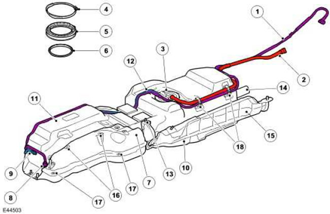
| Item name | Spare part catalog number | Description |
| 1 | - | Pipeline connecting the purge valve to the carbon adsorber |
| 2 | - | Fuel tank breather pipe |
| 3 | - | Fuel Pump Module Flange |
| 4 | - | Pump module clamp |
| 5 | - | Pump module cuff |
| 6 | - | Pump module seal |
| 7 | - | Lid |
| 8 | - | Pipe connection - purge valve |
| 9 | - | Pipe connection - fuel supply line |
| 10 | - | Frame |
| 11 | - | Fuel tank |
| 12 | - | Fuel supply line |
| 13 | - | Mounting screws (6 pcs.) |
| 14 | - | Filler neck hose |
| 15 | - | Heat shield |
| 16 | - | Rivet |
| 17 | - | Screw M6 |
| 18 | - | Clamp cover |
The fuel tank is located on the right side of the car body between the gearbox and the right side member. The tank rests on the frame, by means of which the fuel tank assembly is attached to the car body. The working volume of the fuel tank is 86.3 liters.
The frame is attached to the chassis with six screws. When the frame is attached to the chassis, the fuel tank is held against the suspension crossmember by foam pads. A protective cover is attached to the left front corner of the fuel tank for additional protection.
The fuel tank is made of molded plastic with a thickness of at least 3 mm. The fuel tank is a sealed unit with internal access through the flange opening of the pump module at the top of the tank.
The flange assembly consists of a cuff, a clamp and a pump module flange, which contains all external pipe and electrical connections for the internal components of the tank. The flange is sealed by a gasket in the tank opening. To correctly orient the flange, it is necessary to position it so that the arrow on the flange is located between the two marks on the fuel tank adjacent to the opening of the pump module flange. The cuff is located above the flange and is secured with a clamp. The flange, seal, cuff and clamp comply with the sealing requirements of the LEV2 standard.
The flange has an external six-pin connector for connecting fuel level sensors and a fuel pump. This connector is divided into three connectors with a tight fit on the bottom side of the flange. The fuel supply line and breather are connected using a quick-release connector.
A support structure is installed inside the tank to support the internal components of the fuel tank. The support structure contains the fuel pump module, front fuel level sensor, rollover valves (ROV), front jet pump and fuel tank vent valve (FLVV).
The fuel pump module consists of several units. The module includes: a fuel pump, a rear fuel level sensor, a rear jet pump, a pump inlet filter, a second fine-mesh filter and a fuel pressure regulator located in the manifold, which is mounted on a support structure. The pump module assembly and fuel level sensors are supplied only as an assembly; delivery of individual parts of these units is not possible.
Internal components of the fuel tank
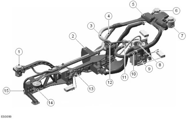
| Item name | Spare part catalog number | Description |
| 1 | - | Right Front Roll Over Valve (ROV) |
| 2 | - | Assembled support structure |
| 3 | - | Corrugated Fuel Tank Vent Valve (FLVV) Breather Tube |
| 4 | - | Corrugated tube of the front inversion valve |
| 5 | - | Fuel Vapor Separator (LVS) |
| 6 | - | Rear Right ROV Valve |
| 7 | - | Rear Left ROV Valve |
| 8 | - | Fuel pump module |
| 9 | - | Rear fuel level sensor |
| 10 | - | T fuel tank breather fitting |
| 11 | - | Connector |
| 12 | - | Fuel Tank Vent Valve (FLVV) |
| 13 | - | Front fuel level sensor |
| 14 | - | Front Left ROV Valve |
| 15 | - | Front jet pump |
The 4.0L V6 engine's ventilation system is identical to that used in models with the 4.4L V8 engine. The ventilation system consists of:
- four rollover valves (ROV)
- one fuel tank vent valve (FLVV)
- one fuel vapor separator (LVS)
The two rear ROV valves are mounted directly to the LVS via rubber grommets and secured with clamps.
The two forward ROV valves are located at the front of the fuel tank and are secured to the main support structure rod with a plastic clamp. Both ROV valves are connected to the LVS with plastic corrugated tubes.
All four ROV valves are connected directly to the LVS. Liquid fuel separated from the vapor in the LVS is drained back to the fuel tank through the FLVV. The LVS is connected to the fuel pump module flange via a corrugated tube.
This allows fuel vapors to escape from the fuel tank during ventilation.
The main purpose of the FLVV valve is to control the filled tank volume. During refueling, fuel vapors pass through the FLVV valve into the LVS. Then, the fuel vapors pass through a corrugated tube from the LVS to the vent nipple of the flange of the fuel pump module. The vent pipe of the flange is connected to a carbon adsorber, which accumulates fuel vapors. When the fuel level in the tank reaches the maximum level during refueling, the FLVV valve closes and prevents fuel vapors from passing through the LVS. This leads to an increase in pressure in the fuel tank, which, in turn, leads to the shutdown of the pump of the filling gun.
Fuel pump module
The fuel pump module is attached to the tank support structure and is located at the bottom of the receiving cup. The pump and fuel level sensors are connected to the external electrical connector via connectors on the bottom of the fuel pump module flange.
The nominal capacity of the pump module is 122 l/h at 12.3 V and the output pressure is 4.5 bar (65.2 lbf/in²).
The fuel pump is supplied with power from the fuel pump relay located in the battery junction box. The relay is controlled by the engine control module and is activated each time the ignition key is turned to position II.
The fuel pump inlet filter is installed in the inlet channel at the bottom of the pump. The filter has a "winged" part located vertically on the side of the pump so that part of the filter is located away from the base of the receiving cup to prevent premature contamination of the filter. The filter has a fine mesh (the cell size is 31 microns) area 70 cm² (10.8 in²).
The second fine-mesh filter is located around the top of the fuel pump. This provides additional cleaning of the fuel before it enters the manifold and fuel distributor. The filter has an electrical connection to ground. Ground is necessary to remove electrostatic charges that may occur on the fine-mesh filter.
The fuel filter has a bypass valve built into it to prevent fuel from returning to the pump when the engine is not running. This helps maintain fuel pressure in the line from the fuel supply line to the fuel rail when the engine is not running.
Fuel level sensors
The sensor is a magnetic passive position sensor (MAPPS) whose signal is a change in resistance in the ground circuit of the fuel gauge. For increased reliability, the sensor is isolated from the fuel to prevent contamination of its contacts. The front and rear fuel level sensors are connected to the external electrical connector on the flange via connectors on the bottom of the fuel pump module flange.
The front sensor is mounted on the front of the fuel tank support structure and is accessible through a hole in the fuel pump flange. The rear sensor is mounted on the side of the receiver cup and is also accessible through a hole in the flange.
NOTE: The new tank comes complete with a front fuel level sensor.
The sensor has an arc with a ceramic surface on which 51 film resistors are mounted. The resistors are connected in series by means of separate contacts. A soft magnetic foil with 51 flexible contacts is mounted at a small distance above the film resistors. A magnet is mounted under the ceramic surface and is fixed to the fuel gauge float lever. When the float lever moves, the magnet moves along an arc along the film resistors. The magnet attracts the flexible contacts to the opposite film resistors and closes the circuit.
Operating principle of the sensor
(The original article is located on the website LRMAN.RU)
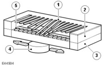
| Item name | Spare part catalog number | Description |
| 1 | - | Magnetic foil |
| 2 | - | Spacer |
| 3 | - | Ceramic surface |
| 4 | - | Magnet |
| 5 | - | Resistive film |
The resistance of the film resistors arranged in a linear arc varies in the range from 51.2 to 992.11 Ohms. The output signal is proportional to the amount of fuel in the tank and the position of the float. The measured resistance is processed in the instrument panel to eliminate the effect of fluctuations in the fuel surface in the tank. The processor monitors the sensor signal and updates the position of the pointer at certain intervals to eliminate constant changes in the position of the pointer due to fluctuations in the fuel surface during braking or turning.
The indicator lamp in the instrument panel comes on when the fuel level in the tank is 10 liters or less.
In the instrument cluster, the fuel level sensor signal is converted into a CAN message as a direct interpretation of the fuel tank content in liters. The ECM uses the CAN message to store additional OBD P misfire detection codes when the fuel level drops below a predetermined value.
Front Fuel Level Sensor Resistance/Fuel Level Gauge Table
NOTE: These values are valid when the vehicle is on a level surface. The fuel gauge readings will change depending on the vehicle tilt.
| Fuel level sensor resistance, Ohm | Nominal reading of the pointer |
| 51 | Empty tank |
| 51 | Low fuel alarm |
| 294 | Half full |
| 798 | Full |
Rear Fuel Level Sensor Resistance/Fuel Level Gauge Table
NOTE: These values are valid when the vehicle is on a level surface. The fuel gauge readings will change depending on the vehicle tilt.
| Fuel level sensor resistance, Ohm | Nominal reading of the pointer |
| 75,5 | Empty tank |
| 120 | Low fuel alarm |
| 280 | Half full |
| 675 | Full |
Fuel pressure regulator
The fuel pressure regulator is located in the manifold inside the fuel tank. The regulator maintains the required pressure of the fuel entering the fuel manifold through the fuel supply line by bypassing some of the fuel back to the front jet pump.
The regulator maintains the fuel pressure at the inlet to the fuel manifold at 4.5 bar, and its operation depends on the pressure at the pump outlet. (65.2 lbf/in²). If the pressure exceeds the specified value, the regulator opens, reducing the pressure at the inlet to the fuel manifold by bypassing some of the fuel to the front jet pump. The regulator must maintain the fuel pressure at an optimal level to ensure proper fuel injection.
Receiving glass
The pickup cup is located at the rear of the fuel tank and carries most of the fuel pump assembly components.
The receiver cup serves as a fuel reservoir that ensures a constant supply of fuel to the fuel pump, regardless of the amount of fuel or the tilt of the car. When the car is on a level surface and the engine is running, there is approximately 400 cm³ in the receiver cup. (24.4 in³). Two jet pumps continuously supply the receiving cup with fuel, ensuring the supply of fuel to the pump.
There is a check valve at the base of the receiving cup. The valve allows fuel from the tank to flow into the receiving cup, but does not release it back into the tank.
Jet pumps
The fuel system has two jet pumps. The front jet pump is located on the support structure at the front of the fuel tank. The rear jet pump is located in the receiving cup under the fuel pump. Both pumps operate based on the Venturi effect, which is created by fuel under pressure equal to the pressure at the outlet of the fuel pump, when passing through the jet pump. As a result, an additional amount of fuel comes from the fuel tank into the receiving cup through holes in the body of the jet pump.
The front jet pump is used mainly when driving the car downhill. The jet pump is connected to the system via a pipe from the fuel manifold and is supplied with fuel released from the fuel supply line by the fuel pressure regulator. The front jet pump takes fuel from the front of the fuel tank and pumps it into the receiving cup, ensuring a continuous supply of fuel to the pump. The jet pump has a nozzle with a diameter of 2.1 mm.
The rear jet pump operates at a pressure equal to the outlet pressure of the fuel pump and pumps some fuel from the rear of the fuel tank back into the pickup bowl.
Rollover Valves (ROV)
The four ROVs are located on the fuel tank support structure and are connected by tubing to the fuel vapor separator. The separator, also mounted on the support structure, is connected by tubing to the fuel tank breather outlet on the pump module flange. The ROVs use check valves that close when the vehicle is turned over, preventing fuel from leaking out of the tank through the breather tube.
Comments on this article