| Item name | Spare part number | Description |
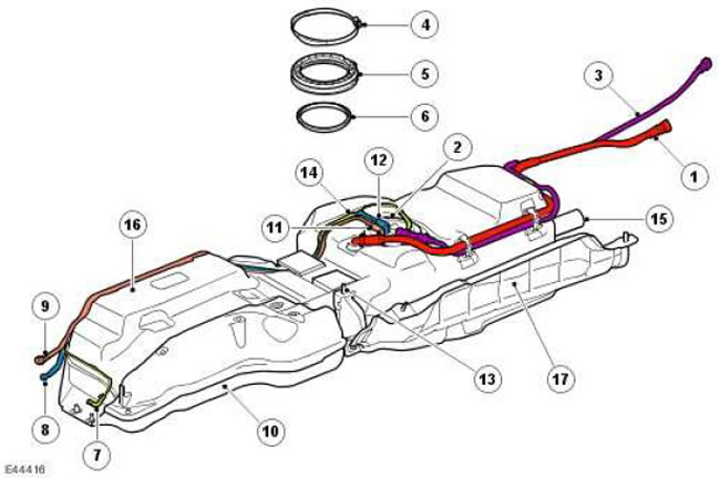
| 1 | - | Fuel tank breather tube |
| 2 | - | Fuel pump module assembly |
| 3 | - | Ventilation pipeline |
| 4 | - | Pump module clamp |
| 5 | - | Pump module collar |
| 6 | - | Pump module seal |
| 7 | - | FBH pump supply line (if available) |
| 8 | - | Pipeline - fuel return |
| 9 | - | Pipeline - fuel supply |
| 10 | - | Frame |
| 11 | - | Fuel supply fitting |
| 12 | - | Fuel return fitting |
| 13 | - | fixing bolt (6 pcs.) |
| 14 | - | Supply pipe fitting FBH (if available) |
| 15 | - | filler hose |
| 16 | - | Fuel tank |
| 17 | - | heat shield |
The fuel tank is located on the right side of the car body between the gearbox and the right side member. The tank rests on the frame, through which the fuel tank assembly is attached to the vehicle body. The working volume of the fuel tank is 82.0 liters.
The frame is attached to the chassis with six screws. When the frame is attached to the chassis, the fuel tank is pressed against the suspension cross member with foam pads. A protective cover is attached to the right front corner of the fuel tank, which provides additional protection.
The fuel tank is made of molded plastic with a minimum thickness of 3 mm. The fuel tank is a sealed unit with internal access through a pump module flange opening at the top of the tank.
The flange assembly includes the lip, yoke, and pump module flange, which contains all external piping and electrical connections for internal tank assemblies. The flange is sealed with a seal in the tank opening. For proper flange orientation, position the flange so that the arrow on the flange is between the two marks on the fuel tank adjacent to the pump module flange hole. The cuff is located above the flange and fastened with a clamp.
The flange has an external six-pin connector for connecting fuel level sensors and a fuel pump. This connector is split into three tight-fit connectors on the underside of the flange. The supply and return fuel lines and ventilation pipelines are connected using two quick-release fittings. The fuel return line fitting has a check valve that prevents fuel from escaping when the vehicle is rolled over and the line is disconnected. If the vehicle is equipped with a flare heater, the third fitting is for connecting the fuel supply line to the flare heater.
A support structure is installed inside the tank, designed to fasten the internal components of the fuel tank. Support structure houses fuel pump module, front fuel level sensor, flip valves (ROV) and front jet pump.
The fuel pump module consists of several assemblies. The module includes: a fuel pump, a rear fuel level sensor, a rear jet pump, a pump inlet filter and a fuel pressure regulator installed in the manifold located on the chassis. The pump module assembly and fuel level sensors are supplied only as an assembly, the delivery of individual parts of these assemblies is not possible.
Fuel tank internals
| Item name | Spare part number | Description |
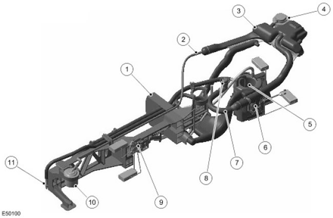
| 1 | - | Complete support structure |
| 2 | - | Corrugated tube front flip valve |
| 3 | - | Fuel vapor separator (LVS) |
| 4 | - | Rear flip valve (ROV) |
| 5 | - | fuel pump module |
| 6 | - | Rear fuel gauge |
| 7 | - | Corrugated Tank Breather Tube |
| 8 | - | Fuel tank breather fitting |
| 9 | - | Front fuel gauge |
| 10 | - | Front ROV Valve |
| 11 | - | Front jet pump |
The ventilation system of the TdV6 engine is different from the ventilation systems of gasoline engines. The TdV6 engine ventilation system includes:
- two flip valves (ROV)
- one vapor separator (LVS)
- breather trough
The rear ROV valve is located in the right rear corner of the fuel tank. It is mounted directly on the LVS by means of a rubber grommet and secured with a clamp.
The front ROV valve is located in the left front corner of the fuel tank. It is attached with a plastic retainer to the main rod of the supporting structure. The ROV valve is connected to the LVS via a corrugated tube.
Both ROVs are connected directly to the LVS. The liquid fuel released from the vapors in the LVS is drained back to the fuel tank through the front valve of the ROV.
The LVS outlet vent is connected to the bottom of the fuel tank flange. Further, the ventilation pipeline is laid from the flange to the upper part of the filler neck. Through this pipeline, the pressure in the tank is maintained at atmospheric level during normal operation of the fuel tank. Through this pipeline, air enters the tank as fuel is used up.
The main purpose of the fuel tank breather fitting is to control the filled volume of the tank. When refueling, fuel vapor from the fuel tank enters the filler neck through the breather fitting and the breather tube. When the fuel in the tank reaches the top level and fills the breather fitting, the latter closes. Due to the blockage of the breather fitting, the pressure in the tank increases, which, in turn, leads to the shutdown of the nozzle pump.
Fuel pump module
The fuel pump is fixed to the tank support structure and is located at the bottom of the receiving cup. The pump and fuel level sensors are connected to an external electrical connector through connectors on the bottom of the fuel pump module flange.
The nominal output of the pump module is 70 l/h at 12.3 V and the outlet pressure is 0.5 bar (7.25 lbf/in2).
The fuel pump is powered from the fuel pump relay located in the battery junction box. The relay is controlled by the engine control module and turns on each time the ignition key is turned to position II.
The filter is installed in the inlet channel at the bottom of the pump. The filter has "winged" vertically on the side of the pump so that the filter part is away from the base of the suction cup to prevent premature filter contamination. The filter consists of two parts: a regular filter and a bypass filter. The conventional filter has a fine mesh (cell size is 31 microns) area 70 cm2 (10.8 inch2). The bypass filter has a coarse mesh (cell size is 300 microns) area 4 cm2 (0.62 inch2). In cold weather, wax can form in the fuel, which restricts the passage of the fuel through the fine mesh filter. In this case, the bypass channel opens, allowing the fuel to pass through the coarse mesh.
There are three fittings on the top of the fuel pump module. One fitting is the outlet of the fuel pump, through which fuel is supplied to the manifold. The second port is designed to return pressurized fuel at the pump outlet from the manifold to the rear jet pump through the pump module housing. Through the third fitting, fuel returns from the pressure regulator to the receiving cup when the regulator opens as a result of overpressure at the pump outlet.
Fuel level sensors
The sensor is a passive magnetic position sensor (MAPPS), the signal of which is a change in the resistance of the mass circuit of the fuel gauge. To increase reliability, the sensor is isolated from the fuel so that its contacts do not get dirty. The front and rear fuel level sensors are connected to the external electrical connector on the flange through connectors on the bottom of the fuel pump module flange.
The front sensor is mounted on the front of the fuel tank support structure and can be accessed through a hole in the fuel pump flange. The rear sensor is mounted on the side of the sump and is also accessible through a hole in the flange.
NOTE: A new tank comes complete with a front fuel gauge.
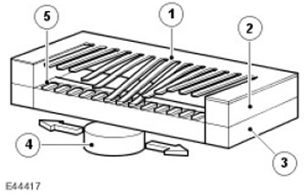
The sensor has an arc with a ceramic surface, on which 51 film resistors are installed. The resistors are connected in series through separate contacts. At a short distance above the film resistors, a soft magnetic foil with 51 flexible contacts is mounted. Under the ceramic surface there is a magnet attached to the fuel indicator float lever. When the float lever moves, the magnet moves in an arc along the film resistors. The magnet pulls the flexible contacts to opposite film resistors and completes the circuit.
The principle of operation of the sensor
| Item name | Spare part number | Description |
| 1 | - | magnetic foil |
| 2 | - | Spacer |
| 3 | - | ceramic surface |
| 4 | - | Magnet |
| 5 | - | Resistive film |
The resistance of film resistors located along a linear arc varies in the range from 51.2 to 992.11 ohms. The output signal is proportional to the amount of fuel in the tank and the position of the float. The measured resistance is processed in the instrument panel to eliminate the influence of fluctuations in the surface of the fuel in the tank. The processor monitors the sensor signal and updates the position of the pointer pointer at regular intervals to ensure that the pointer position does not constantly change due to fluctuations in the fuel surface when braking or turning.
The control lamp in the instrument panel turns on when the fuel level in the tank is 10 liters or less.
In the instrument panel, the signal from the fuel level sensor is converted into a CAN·message in the form of a direct interpretation of the contents of the fuel tank in liters.
Front Fuel Level Sensor Resistance/Fuel Gauge Reading Chart
NOTE: These values are valid when the vehicle is on a level surface. The fuel gauge reading changes as the vehicle tilt changes.
| Fuel level sensor resistance, Ohm | Rated pointer reading |
| 51,2 | empty tank |
| 67 | Low Fuel Alarm (17 l) |
| 281 | half filled |
| 872 | Full |
Rear Fuel Level Sensor Resistance/Fuel Gauge Reading Chart
NOTE: These values are valid when the vehicle is on a level surface. The fuel gauge reading changes as the vehicle tilt changes.
| Fuel level sensor resistance, Ohm | Rated pointer reading |
| 75 | empty tank |
| 150 | Low Fuel Alarm (17 l) |
| 267 | half filled |
| 768 | Full |
Fuel pressure control
The fuel pressure regulator is located in the manifold inside the fuel tank. The regulator controls the fuel pressure in the fuel supply line of the high pressure fuel pump. If the pressure at the pump outlet becomes excessive, the regulator directs part of the fuel back into the receiving cup.
The regulator maintains the fuel pressure at the inlet of the high pressure fuel pump at a maximum of 0.5 bar (7.25 lbf/in2), and the operation of the regulator depends on the pressure at the pump outlet. If the pressure exceeds the specified value, the regulator opens, lowering the pressure at the inlet of the high pressure fuel pump by bypassing some of the fuel into the receiving cup. The main purpose of the regulator is to protect the high pressure fuel pump from the action of high fuel pressure, pumped by the low pressure fuel pump when high voltage is applied to it.
Receiving cup
The cup is located at the rear of the fuel tank and holds most of the fuel pump assemblies.
The sump serves as a fuel reservoir that provides a constant supply of fuel to the fuel pump, regardless of the amount of fuel or the tilt of the vehicle. When the vehicle is on a level surface and the engine is running, there is approximately 400 cm3 in the receiver (24.4 inch3). Two jet pumps continuously supply fuel to the jet cup, ensuring that fuel is supplied to the pump.
A check valve is located at the base of the receiving cup. The valve passes fuel from the tank into the receiving cup, but does not release it back into the tank.
Jet pumps
The fuel system has two jet pumps. The front jet pump is located on a support structure at the front of the fuel tank. The rear jet pump is located in the receiving cup under the fuel pump. Both pumps operate on the basis of the Venturi effect created by fuel at a pressure equal to the pressure at the outlet of the fuel pump as it passes through the jet pump. As a result, an additional amount of fuel flows from the fuel tank into the receiving cup through the holes in the jet pump housing.
The front jet pump is mainly used when driving downhill. The jet pump is connected to the fuel manifold by a pipeline through which fuel is supplied at a pressure equal to the pressure at the outlet of the fuel pump. Positioned at the front of the fuel tank, it collects fuel from the front of the tank and pumps it into the sump, providing a continuous supply of fuel to the pump. The jet pump has a nozzle with a diameter of 1 mm.
The rear jet pump operates at a pressure equal to the fuel pump outlet pressure and pumps some fuel from the rear of the fuel tank back into the canister.
Turnover valves (ROV)
Two ROVs are located on the fuel tank support structure and are piped to the fuel vapor separator. The separator, also mounted on the support structure, is piped to the fuel tank breather outlet on the pump module flange. ROV valves use check valves that close when the vehicle is rolled over, preventing fuel from escaping from the tank through the breather tube.
Comments on this article