car logo Ford
car logo Volkswagen
car logo BMW
car logo Opel
car logo Audi
car logo Toyota
car logo Peugeot
English Русский
Български
Беларускі
Український
Српски
Hrvatski
Română
Polski
Slovenský
Magyar


Main
Freelander
Discovery
Range Rover
Defender
Contacts
Articles

Removal and installation the fuel tank 2.7L (Discovery 3)

 
  • Main
  • Discovery
  • Discovery 3
  • Power unit
  • Fuel tank and lines
  • Removal and installation the fuel tank 2.7L
 
        0  
Contents: Removal ⇩ Installation ⇩

Removal


All cars

1. Disconnect the ground cable from the battery. For more information, refer to Specification.

2. Drain the fuel from the fuel tank. For more information, refer to Draining the Fuel Tank (19.55.02)

3.
CAUTION: Never work on a vehicle supported only by a jack. Always support the vehicle with special stands.


Raise and support the vehicle.

4. Remove the fuel tank heat shield. Remove 3 bolts and 2 nuts.
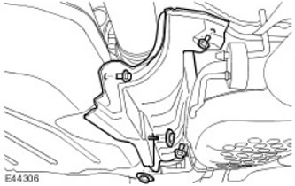
4. Remove the fuel tank heat shield. Remove 3 bolts and 2 nuts.


5.
CAUTION: Before disconnecting or disassembling parts, make sure that the area around the contact surfaces and connections is clean. To avoid contamination of the system, close all open connections with plugs.


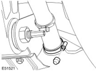
Disconnect the fuel tank filler neck from the filler neck hose.
  • Remove the tamper-resistant cover.
  • Remove and discard the hose clamp.
Remove and discard the hose clamp.


6.
CAUTION: Secure the assembly to a transmission jack.


Lower the fuel tank using a transmission jack. Remove the 5 bolts.
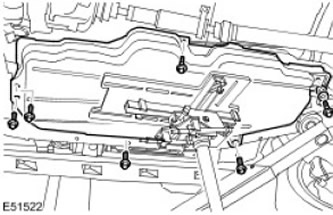
Lower the fuel tank using a transmission jack. Remove the 5 bolts.


7. Release the parking brake cable emergency release cable. Release it from the 4 clamps.

8.
NOTE: Remember the position of the part.


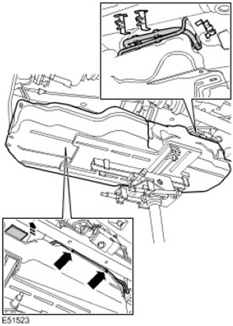
Disconnect the fuel tank vent line and fuel line.
  • Remove the holders.
  • Release from the clamps.
  • Remove the adhesive tape.
Remove the adhesive tape.


9.
CAUTION: Before disconnecting or disassembling parts, make sure that the area around the contact surfaces and connections is clean. To avoid contamination of the system, close all open connections with plugs.


Disconnect the 2 fuel tank vent lines. Release the clamp.

Cars with fuel-fired auxiliary heater

10.
CAUTION: Before disconnecting or disassembling parts, make sure that the area around the contact surfaces and connections is clean. To avoid contamination of the system, close all open connections with plugs.


Disconnect the fuel line from the fuel fired auxiliary heater. Release the clamp.

All cars

11.
CAUTION: Before disconnecting or disassembling parts, make sure that the area around the contact surfaces and connections is clean. To avoid contamination of the system, close all open connections with plugs.


Disconnect 2 fuel lines. Release 2 clamps.

12. Disconnect the fuel pump module electrical connector.

13. Remove the fuel tank.
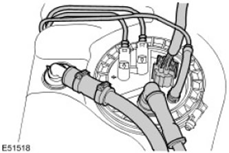
13. Remove the fuel tank.


14.
NOTE: Do not perform further disassembly if the part is removed only for access.


With assistance, remove the fuel tank from the transmission jack.

15.
CAUTION: Before disconnecting or disassembling parts, make sure that the area around the contact surfaces and connections is clean. To avoid contamination of the system, close all open connections with plugs.


NOTE: Remember the position of the part.


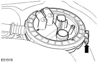
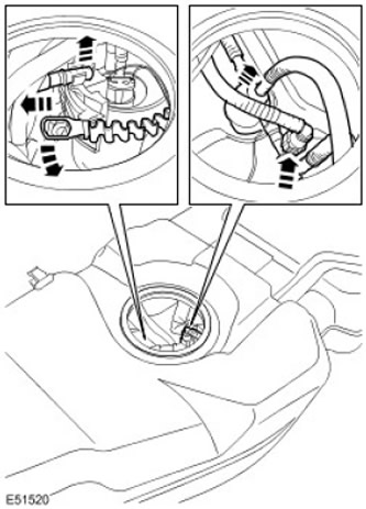
Release the fuel pump module access flange.
  • Loosen the screw.
  • Remove the clamp.
Remove the clamp.


16.
CAUTION: Before disconnecting or disassembling parts, make sure that the area around the contact surfaces and connections is clean. To avoid contamination of the system, close all open connections with plugs.


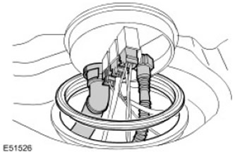
Remove the fuel pump module access flange.
  • Disconnect the ventilation line.
  • Disconnect the fuel supply line.
  • Disconnect the 3 electrical connectors.
  • Remove and discard the sealing ring.
Remove and discard the sealing ring.


17. Remove the fuel pump module.
  • Release the tape.
  • Release the fuel pressure regulator.
  • Disconnect 2 fuel lines.
Disconnect 2 fuel lines.


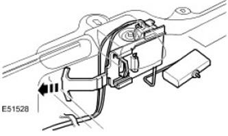
18. Remove the front fuel tank level sensor.
  • Release the wire.
  • Release the clamp.
Release the clamp.


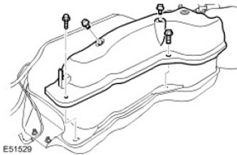
19. Remove the fuel tank bracket.


  • Remove 2 clamps.
  • Remove two bolts.
  • Remove the mounting plate.
Remove the mounting plate.


Installation


All cars

1. Install the fuel tank bracket.
  • Install the support plate.
  • Install the clamps.
  • Tighten the bolts (tightening torque 10 Nm).
2. Install the front fuel tank level sensor.
  • Secure the clamp.
  • Secure the wire.

3. Install the fuel pump module.
  • Connect the fuel lines.
  • Secure with tape.
  • Secure the fuel pressure regulator.
4. Install the fuel pump module access flange.
  • Clean the contact surfaces of the parts.
  • Install a new seal.
  • Connect the 3 electrical connectors.
  • Connect the fuel supply line.
  • Connect the ventilation line.
5.
CAUTION: Make sure the seal is installed correctly.


NOTE: Align the part to its original position.


Secure the fuel pump module access flange.
  • Install the clamp.
  • Tighten the screw (tightening torque 4 Nm).
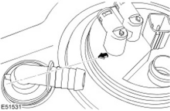
Tighten the screw (tightening torque 4 Nm).


6. With assistance, place the fuel tank on the transmission jack.


7. Place the fuel tank on the vehicle.

8. Connect the fuel lines. Secure with a clamp.

Cars with fuel-fired auxiliary heater

9. Attach the fuel line of the fuel-fired auxiliary heater. Secure with a clamp.

All cars

10. Connect the ventilation lines. Secure with a clamp.

11. Connect the electrical connector.

12. Secure the ventilation line and fuel line.
  • Secure with clamps.
  • Install the holders.
  • Install the self-adhesive tape.
13. Secure the parking brake cable emergency release cable. Secure with 4 clamps.

14. Install the fuel tank. Tighten the bolts. (tightening torque 45 Nm).

15.
CAUTION: Tighten the tamper-resistant clamp until the hex head breaks.


Attach the fuel tank filler neck. Install a new clamp.

16. Install the fuel tank heat shield.
  • Tighten the bolts (tightening torque 5 Nm).
  • Tighten the nuts (tightening torque 3 Nm).
17. Fill the fuel tank with fuel. For more information, refer to Draining the Fuel Tank (19.55.02)

18. Bleed the fuel system. For more information, refer to Bleeding the Low-Pressure Fuel System (19.50.07)


This article is available at russian, bulgarian, belarusian, ukrainian, serbian, croatian, romanian, polish, slovak, hungarian
Article review: Saveliy Ushakov


Previous articles
Specification 4.0L
Specification 4.4l
Specification 2.7l
Device and technical description 4.0L
Fuel tank assembly 4.0l
Fuel tank filler neck 4.0L
Device and technical description 4.4L
Fuel tank assembly 4.4l

Current article
Removal and installation the fuel tank 2.7L


Similar articles from Land Rover repair manuals:
• Fuel Tank Leak Collection System Pump Filter Freelander 2 (2006-2014)
• Fuel Tank Leak Detection System (EVAPS) Freelander 1 (1997-2006)
• Fuel Tank Leakage Monitoring Unit (DMTL Unit) Range Rover 3 (2001-2012)
• Fuel tank specifications Defender 2007+ (2007-2016)

Comments on this article


No comments yet


How much will 17 + 47 =


Discovery 3 
  • General information
  • Using the manual
  • Precautionary measures
  • Service Information
  • Technique
  • Health protection
  • Road test
  • Identification codes
  • Jacking and lifting
  • Maintenance - diesel
  • Maintenance - petrol
  • Chassis
  • Suspension
  • Front suspension
  • Rear suspension
  • Wheels and tires
  • Dynamic suspension
  • Cardan shaft
  • Rear drive axle
  • Front drive axle
  • Front axle axles
  • Rear axle axles
  • Brake system
  • Parking brake
  • Hydraulic brake
  • Vacuum brake booster
  • Anti-lock braking system
  • Steering
  • Steering column
  • Power unit
  • Petrol engine 4.0L
  • Petrol engine 4.4L
  • Diesel engine 2.7L
  • Engine cooling
  • Fuel supply
  • Drive units
  • Launch system
  • Ignition system
  • Emission reduction
  • Air filtration
  • Fuel vapor control
  • Electronic control part
  • Car gearbox
  • Clutch
  • All-wheel drive systems
  • Transfer case
  • Exhaust system
  • Fuel tank and lines
  • Acceleration control
  • Electrical equipment
  • Climate control
  • Instruments and control lamps
  • Battery and charging system
  • Information system
  • Lighting and headlights
  • Power distribution
  • Electronic Function Group
  • Body and coating
  • Body elements
  • Interior and body trim
  • Mirrors and glasses
  • Seats
  • Instrument panel and console
  • Handles and locks
  • Windshield wipers and washers
  • Sunroof and bumpers
  • Safety system
  • Body repairs
  • Repair of front end elements
  • Repair of back elements
  • Side panel repair
  • Frame and body mount

Discovery 1 
  • General information
  • Technical specifications
  • Introduction to manual
  • Troubleshooting
  • Power unit
  • Diesel engine Tdi
  • Petrol engine V8i (3.9 l)
  • Petrol engine V8i (4.0 l)
  • Petrol engine Mpi
  • Reducing harmful emissions
  • Fuel system Tdi
  • Fuel system MFi
  • Fuel system SFi
  • Fuel system MPi (MEMS)
  • Cruise control
  • Cooling system (Tdi)
  • Cooling system (V8i)
  • Cooling system (MPi)
  • Exhaust system
  • Transmission
  • Clutch
  • Manual gearbox R380
  • Manual gearbox LT 77
  • Transfer case LT230T
  • Automatic gearbox
  • Cardan shaft
  • Rear axle
  • Front axle
  • Chassis
  • Steering system
  • Front suspension
  • Rear suspension
  • Brake system
  • Wheels and tires
  • Body and interior
  • Passive safety
  • Doors, locks and windows
  • Exterior body parts
  • Interior trim details
  • Seats
  • Electrical equipment
  • Heating and ventilation
  • Air conditioning
  • Windscreen wipers
  • Starting and charging system
  • Equipment and devices
  • Lighting and headlights


LRman.ru © 2013-2026 | Mobile version | Free Lander | Discovery | Range Rover | Defender | Contacts | | Sitemap |
Car repair and service instructions Land Rover: Freelander, Discovery, Range Rover, Defender
We use cookies to make pages load faster and provide a more user-friendly experience 🍪