Contents: Removal ⇩ Installation ⇩
Removal
WARNING: The car must be in a well-ventilated, closed area. Signs "No smoking! Gasoline fumes!" must be posted around the car.
CAUTION: Do not carry or use a cell phone when working with any fuel-related parts or in the immediate vicinity of such parts. In such situations, highly flammable vapors are always present, which can ignite. Failure to follow these instructions may result in personal injury.
WARNING: Do not smoke or carry a lighted cigarette or open flame of any type when working on or near fuel-related items. Highly flammable vapors are always present in such situations and may ignite. Failure to follow these instructions may result in injury.
CAUTION: Some fuel will inevitably spill during this operation. Make sure that all necessary precautions are taken to prevent fire and explosion.
CAUTION: Before disconnecting or disassembling parts, make sure that the area around the contact surfaces and connections is clean. To avoid contamination of the system, close all open connections with plugs.
1. Disconnect the ground cable from the battery. For more information, refer to Specification.
2. Drain the fuel from the fuel tank. For more information, refer to Draining the Fuel Tank (19.55.02)
3.
CAUTION: Never work on a vehicle supported only by a jack. Always support the vehicle with special stands.
Raise and support the vehicle.
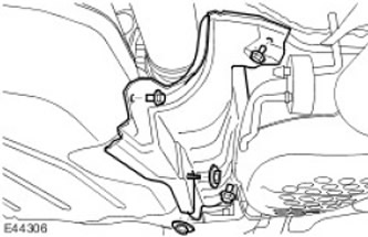
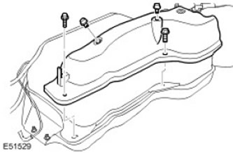
4. Remove the fuel tank heat shield. Remove 3 bolts and 2 nuts.
5.
CAUTION: Before disconnecting or disassembling parts, make sure that the area around the contact surfaces and connections is clean. To avoid contamination of the system, close all open connections with plugs.
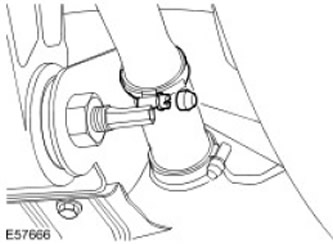
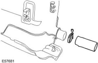
Disconnect the fuel tank filler neck from the filler neck hose.
- Remove the tamper-resistant cover.
- Remove and discard the hose clamp.
6.
CAUTION: Before disconnecting or disassembling parts, make sure that the area around the contact surfaces and connections is clean. To avoid contamination of the system, close all open connections with plugs.
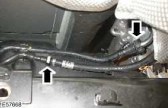
Disconnect the quick-disconnect connection of the fuel supply line and the purge line at the front of the fuel tank.
7.
CAUTION: Before disconnecting or disassembling parts, make sure that the area around the contact surfaces and connections is clean. To avoid contamination of the system, close all open connections with plugs.
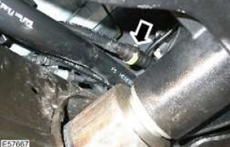
Disconnect the fuel tank vent line.
8. Disconnect the fuel tank wiring harness.
9. Release the parking brake cable emergency release cable. Release it from the 4 clamps.
10. Remove the 2 parking brake cable emergency release cable clamps.

11.
CAUTION: Secure the assembly to a transmission jack.
CAUTION: Do not lower the fuel tank lower than 250 mm. (9.75 inches)
NOTE: Please note that there are two washers on the rear bolt.
Using a transmission jack, lower the fuel tank enough to gain access to the top. Remove the 6 bolts.
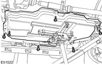
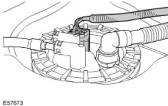
12. Disconnect the fuel pump module electrical connector.
13. Release the purge line from the top of the fuel tank.
- Remove the adhesive tape.
- Release from 5 clamps.
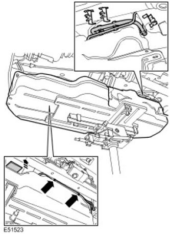
14. Remove the fuel tank.
15.
NOTE: Do not perform further disassembly if the part is removed only for access.
With assistance, remove the fuel tank from the transmission jack.
16.
CAUTION: Before disconnecting or disassembling parts, make sure that the area around the contact surfaces and connections is clean. To avoid contamination of the system, close all open connections with plugs.
Remove the fuel tank vent line.
- Disconnect the quick release coupling.
- Release from 3 clamps.
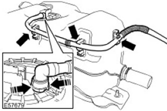
17.
CAUTION: Before disconnecting or disassembling parts, make sure that the area around the contact surfaces and connections is clean. To avoid contamination of the system, close all open connections with plugs.
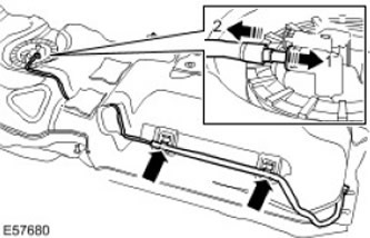
Disconnect the fuel supply line.
- Disconnect the quick release coupling.
- Release from 2 clamps.
18.
CAUTION: Before disconnecting or disassembling parts, make sure that the area around the contact surfaces and connections is clean. To avoid contamination of the system, close all open connections with plugs.
NOTE: Remember the position of the part.
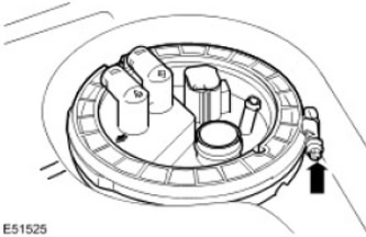
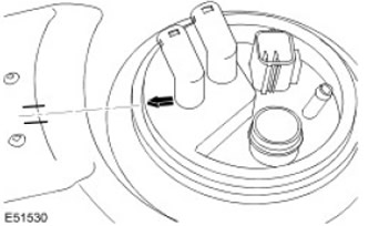
Release the fuel pump module access flange.
- Loosen the screw.
- Remove the clamp.
19.
CAUTION: Before disconnecting or disassembling parts, make sure that the area around the contact surfaces and connections is clean. To avoid contamination of the system, close all open connections with plugs.
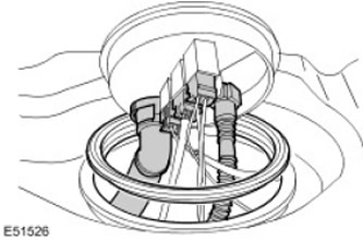
Remove the fuel pump module access flange.
- Disconnect the ventilation line.
- Disconnect the fuel supply line.
- Disconnect the 3 electrical connectors.
- Remove and discard the sealing ring.
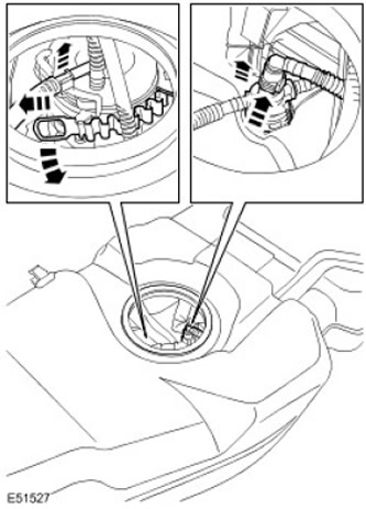
20. Remove the fuel pump module.
- Release the tape.
- Release the fuel pressure regulator.
- Disconnect 2 fuel lines.
21. Remove the front fuel tank level sensor.
- Release the wire.
- Release the clamp.
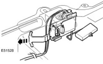
22.
CAUTION: Before disconnecting or disassembling parts, make sure that the area around the contact surfaces and connections is clean. To avoid contamination of the system, close all open connections with plugs.
Remove the filler neck hose.
- Remove the tamper-resistant cover.
- Remove and discard the hose clamp.
23. Remove the fuel tank bracket.
- Remove 2 clamps.
- Remove two bolts.
- Remove the mounting plate.
Installation
1. Install the fuel tank bracket.
- Install the support plate.
- Install the clamps.
- Tighten the bolts (tightening torque 3.5 Nm).
CAUTION: Tighten the tamper-resistant clamp until the hex head breaks.
Install the filler hose. Install a new clamp.
3. Install the front fuel tank level sensor.
- Secure the clamp.
- Secure the wire.
- Connect the fuel lines.
- Secure with tape.
- Secure the fuel pressure regulator.
- Clean the contact surfaces of the parts.
- Install a new seal.
- Connect the 3 electrical connectors.
- Connect the fuel supply line.
- Connect the ventilation line.
CAUTION: Make sure the seal is installed correctly.
Secure the fuel pump module access flange.
- Install the clamp.
- Tighten the screw (tightening torque 4 Nm).
7. Install the fuel supply line.
- Connect the quick-release coupling.
- Secure with 2 clamps.
- Connect the quick-release coupling.
- Secure with 3 clamps.
10. Place the fuel tank on the vehicle.
11. Secure the purge line to the top of the fuel tank.
- Secure with clamps.
- Install the self-adhesive tape.
13.
NOTE: Please note that there are two washers on the rear bolt.
Install the fuel tank. Tighten the bolts. (tightening torque 45 Nm).
14. Install 2 parking brake cable emergency release cable clamps.
15. Secure the parking brake cable emergency release cable. Secure with 4 clamps.
16. Secure the fuel tank wiring harness.
17. Connect the fuel tank vent line.
18. Connect the fuel supply line and the purge line.
19.
CAUTION: Tighten the tamper-resistant clamp until the hex head breaks.
Attach the fuel tank filler neck. Install a new clamp.
20. Install the fuel tank heat shield.
- Tighten the bolts (tightening torque 6 Nm).
- Tighten the nuts (tightening torque 3 Nm).
Comments on this article