Special tool
 310-123 Locking Ring, Fuel Tank 310-123 Locking Ring, Fuel Tank |
General Equipment: Powertrain Jack
Fuel may still remain in the fuel tank after draining. Avoid open source of flame, sparks or flammable substances.
Extreme cleanliness must be observed when handling these elements. Plug all openings. Use new caps.
NOTE: The illustrations may differ in some details, but the fundamental points are completely true.
Removing
All vehicles
1. Disconnect the battery ground wire. Refer to procedure: Specifications (414-00 Charging system - General information, Specifications).
2. Drain the fuel from the fuel tank. Refer to procedure: Emptying the fuel tank (310-00 Fuel supply system - General information, General procedures).
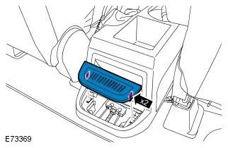
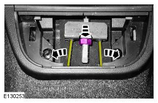
3. Remove the coin tray.
4. Turn away an adjusting nut and disconnect cables of a parking brake from a compensator.
5. Fold forward a pillow of the right back seat.
6. Remove the carpet and remove the bushing.
Vehicles with fuel-fired auxiliary heater
7.
Extreme cleanliness must be observed when handling these elements. Plug all openings. Use new caps.
All vehicles
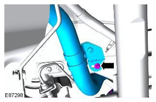
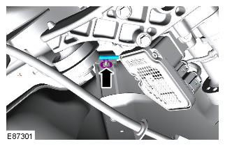
8. Disconnect the electrical connector and ventilation hose.
9. Raise the vehicle.
WARNING: Do not work on or under a vehicle that is only supported by a jack. Always place secure supports under the vehicle.
10. Remove the exhaust system. Refer to Procedure: Exhaust System (309-00A Exhaust system - 3.2L NA - I6, Removal and installation).
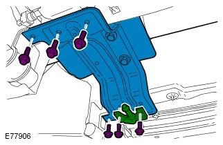
11.
12. Tightening torque: 40 Nm
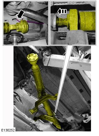
WARNING: Do not use a lever on the driveshaft pivots to disengage the transfer case or rear differential flanges.
Secure the cardan shaft with suitable tires. Use new bolts.
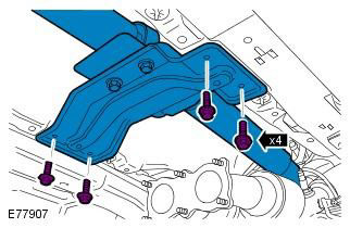
13. Tightening torque: 25 Nm
NOTE: All vehicles up to VIN 180237 and all vehicles with TD4 engine and automatic transmission from VIN 180238
14. Tightening torque: 25 Nm
NOTE: This operation is performed with an assistant.
15. Squeeze the middle joint of the cardan shaft. Tie the driveshaft to the right side of the car.
Make sure the center joint of the driveshaft is compressed. Failure to follow this instruction may result in damage to this component. To avoid damage to the pivot or boot, do not allow the drive shaft to hang unsecured on one side.
16. Tightening torque: 25 Nm
NOTE: Vehicles with TD4 engine and manual transmission from VIN 180238
17.
18.
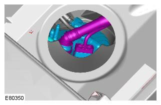
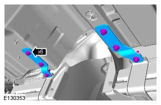
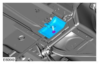
19. Disconnect the parking brake cables from the holder on the fuel tank.
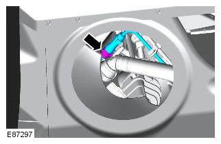
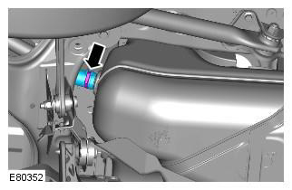
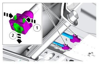
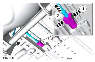
20. Remove the fuel line cap.
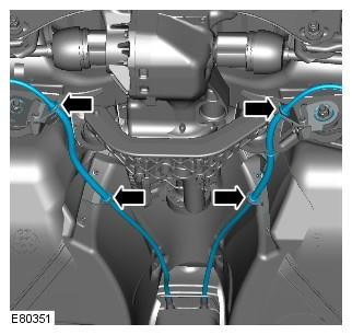
21. Disconnect 2 fuel lines.
Extreme cleanliness must be observed when handling these elements. Plug all openings. Use new caps.
Vehicles with fuel-fired auxiliary heater
22.
Extreme cleanliness must be observed when handling these elements. Plug all openings. Use new caps.
All vehicles
23.
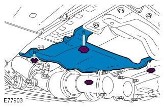
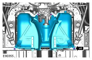
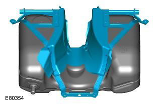
24. Remove the fuel tank. General equipment: Powertrain Jack. Tightening torque: 25 Nm
WARNING: This step requires the assistance of a second mechanic.
CAUTION: Use new bolts.
25. Remove the fuel tank cushion.
NOTE: Do not proceed with disassembly if the element is being removed only to gain access.
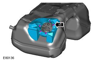
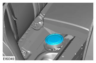
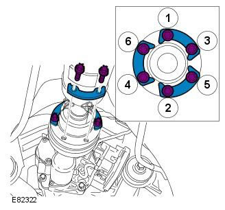
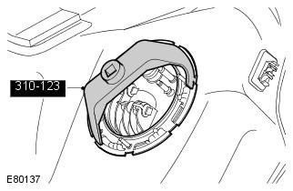
26. Remove the retaining ring of the fuel pump module. Special tool: 310-123. Tightening torque: 200 Nm
CAUTION: These items must be handled with the utmost cleanliness.
27. Disconnect the fuel filter.
CAUTION: A new O-ring must be installed.
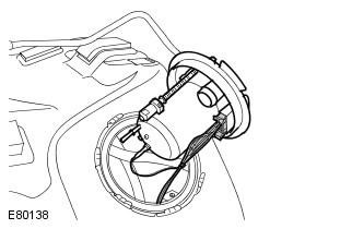
28. Remove the fuel filter.
NOTE: Gasoline engine shown, diesel engine similar.
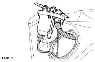
29. Remove the fuel pump module.
NOTE: Gasoline engine shown, diesel engine similar.
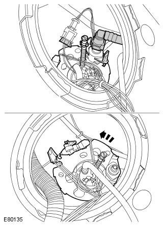
30.
- Push down to release the fuel gauge from the clip.
- Slide the fuel gauge assembly forward to release it from the bracket.
- Remove the fuel gauge from the tank.
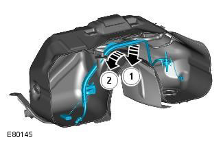
31. Remove the frame of the fuel tank.
Installation
1. Installation is carried out in the reverse order.
2. Fill the fuel tank with fuel.
3. Adjust the parking brake. Refer to Procedure: Parking Brake Cable Adjustment (206-05 Parking Brake and Parking Brake Actuator, General Procedures).
Comments on this article