Removing
1. Disconnect the wire "masses" from the battery.
For more information, see the chapter: Disconnecting and connecting the battery (414-01 Battery, Battery Mount and Wires, General Procedures).
2. Remove the right front seat cushion.
For more information, see chapter: Front seat cushion (501-10 Seat, Removal and installation).
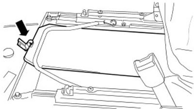
3. Remove the anti-lock brake module cover (ABS). Release the clamp.
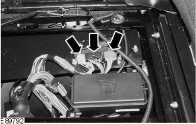
4. Disconnect the three electrical connectors from the ABS module.
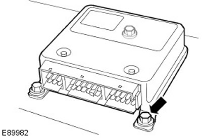
5. Remove the ABS module. Turn out 3 bolts.
Installation
1. Install the ABS module. Tighten the bolts (tightening torque 10 Nm).
2. Connect electric sockets of the module ABS.
3. Install the ABS module cover. Lock the clamp.
4. Install the right front seat cushion.
For more information, see chapter: Front seat cushion (501-10 Seat, Removal and installation).
5. Connect the wire "masses" to the battery.
For more information, see the chapter: Connecting the Battery (414-01 Battery, Battery Mount and Wires, General Procedures).
Comments on this article