Contents: Removal ⇩ Installation ⇩
Removal
1. Place an absorbent cloth under the modulator to collect any spilled liquid.
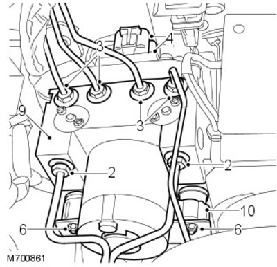
2. Disconnect the two nipple connections of the inlet brake lines on the modulator side on the pump side.
3.
CAUTION: Cap connections.
Disconnect the four brake outlet line nipple connections on top of the modulator.
4. Disconnect the two electrical connectors at the back of the modulator.
5. Loosen the nut securing the rear part of the modulator to the support bracket.
6. Unscrew the two nuts securing the front part of the modulator to the support bracket.
7. Remove the modulator from the support bracket.
8. Disconnect the electrical connector at the base of the modulator.
9. Remove the modulator.
10. Remove the three rubber mounts from the old modulator and install them on the new one.
Installation
1. Install the modulator on the support bracket and connect the electrical connector.
2. Install the modulator on the support bracket and tighten the nuts to 9 Nm.
3. Connect the two electrical connectors at the back of the modulator.
4. Remove the plugs from the brake lines and modulator.
5. Clean the brake line connections.
6. Connect the brake line nipples to the modulator, making sure the lines are connected to the correct ports.
7. Tighten all connections to 14 Nm.
8.
NOTE: To ensure proper operation, the ABS system MUST be tested using the TestBook program.
Bleed the brake system.
For more information, refer to the chapter: Bleeding the Brake System (206-00 Brake System - General Information, General Procedures).
Comments on this article