car logo Ford
car logo Volkswagen
car logo BMW
car logo Opel
car logo Audi
car logo Toyota
car logo Peugeot
English Русский
Български
Беларускі
Український
Српски
Hrvatski
Română
Polski
Slovenský
Magyar


Main
Freelander
Discovery
Range Rover
Defender
Contacts
Articles

The principle of operation of the cooling system (Freelander 2)

 
  • Main
  • Freelander
  • Freelander 2
  • Power unit
  • Description of the cooling system
  • The principle of operation of the cooling system
 
        0  
Contents: Cold engine ⇩ Normal engine operating temperature ⇩
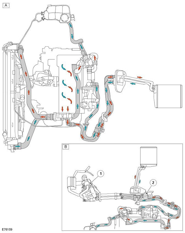
Coolant flow in the cooling system at normal operating temperature:

Coolant flow in the cooling system at normal operating temperature:


Pos.Spare part numberName
A-Cooling system (vehicles for moderate climates)
B-Additional cooling system components (vehicles for cold climates)
1-FFBH
2-Additional coolant pump

Cold engine


When the engine is started, the coolant pump is driven by the timing belt. It circulates coolant through the cylinder block, oil cooler and cylinder head. Coolant also passes through the climate control system heater circuit and through the EGR heat exchanger. The thermostat is in the closed position and prevents coolant from returning from the engine to the radiator.

When the thermostat is closed, the bypass valve opens, directing the returning coolant through the temperature control module and coolant manifold to the coolant pump housing. The coolant continues to circulate and is gradually heated by the engine. Gases present in the cooling system exit through the temperature control module air outlet line to the expansion tank.

The increase in coolant temperature is sensed by the thermostat and reflected on the coolant temperature gauge in the instrument cluster via the ECM and the ECT sensor signal.


For more information, refer to the chapter: Instrument cluster (413-01 Instrument cluster, Description and operating principle).

Normal engine operating temperature


As the coolant temperature increases at 83°C, the thermostat begins to react and open. The bypass valve gradually closes. The hot coolant returning from the engine to the thermal control module is now able to flow through the upper hose to the radiator. The flow of hot coolant to the radiator now forces the cold coolant in the radiator and lower hose to flow to the thermal control module.

During the thermostat opening period, there is an initial coolant temperature differential on both sides of the thermostat. The thermostat responds to the temperature differential and partially closes while the bypass valve opens further. The thermostat and bypass valve continue to oscillate as the coolant temperature increases.

(The source of the article is located on the website LRMAN.ru)

At 91°C the thermostat is fully open and the bypass valve is fully closed. The coolant returning from the engine is now fully circulated through the radiator and the lower hose. The coolant passes through the radiator from the right tank to the left tank and is cooled by the air passing through the radiator core. The gases present in the radiator are released through the air outlet line to the expansion tank.

The increase in coolant volume caused by thermal expansion causes the coolant level to rise through the reservoir connecting hose and the fluid then enters the reservoir.


The cooling system temperature is continuously monitored by the ECM via the ECT sensor signal. The ECT signal is used by the ECM to control the cooling fans and regulate fuel delivery. The ECM also controls the fans based on input signals from the automatic transmission fluid temperature sensor, the air conditioning control switch, and the air conditioning pressure sensor. For additional information, refer to: Electronic Engine Controls - 2.2L Diesel (303-14 Electronic Engine Controls - 2.2L Diesel, Description and Operation). For additional information, refer to: Air Conditioning (412-01 Climate Control, Description and Operation).

In addition, the rotation speed of the cooling fan depends on the vehicle speed. The ECM regulates the rotation speed of the cooling fans to compensate for the effect of the air flow. The speed signal is transmitted via the CAN bus from the anti-lock brake system (ABS) module.

When the engine is turned off, the coolant temperature and volume decrease. The thermostat begins to close as soon as the coolant temperature decreases to 89°C and closes completely at 81°C. The coolant level in the reservoir decreases as coolant is drawn from the reservoir to replenish the system.

After the engine is turned off and the coolant pump is stationary, the ECM may continue to keep the cooling fans running for a preset period of time to maintain engine cooling.


This article is available at russian, bulgarian, belarusian, ukrainian, serbian, croatian, romanian, polish, slovak, hungarian
Article review: Roman Mitrofanov


Previous articles
Description of engine cooling
Coolant pump
Temperature control module
Radiator of cross-flow type
Twin Electric Fan Assembly
Engine oil cooler
Expansion tank
Heater radiator for microclimate control

Current article
The principle of operation of the cooling system


Similar articles from Land Rover repair manuals:
• The principle of operation of the system Discovery 3 (2004-2009)
• Cooling system (Mpi engine) Discovery 1 (1989-1998)
• Engine cooling system Range Rover 3 (2001-2012)
• Audio system — description and principle of operation Defender 2007+ (2007-2016)

Comments on this article


No comments yet


How much will 10 + 41 =


Freelander 2 
  • General information
  • Using the manual
  • Repair technique
  • Precautionary measures
  • Road test
  • Fault codes
  • Identification codes
  • Jacking and lifting
  • Maintenance - Diesel
  • Maintenance - petrol
  • Chassis
  • Suspension
  • Front suspension
  • Rear suspension
  • Wheels and tires
  • Terrain response
  • Transmission system
  • Cardan shaft
  • Rear drive axle
  • Rear axle shafts
  • Front axle shafts
  • Brake system
  • Parking brake
  • Hydraulic brake
  • Brake booster
  • Anti-lock braking system
  • Exchange rate stability
  • Steering
  • Steering column
  • Power unit
  • Engine device
  • Engine repair
  • Description of the cooling system
  • Cooling system repair
  • Fuel supply
  • Drive units
  • Launch system
  • Ignition system
  • Exhaust toxicity
  • Air filtration
  • Fuel vapor control
  • Electronic control part
  • Automatic gearbox
  • Gearbox cooling
  • Automatic transmission controls
  • Mechanical transmission
  • Transfer case
  • Exhaust system
  • Fuel tank and lines
  • Speed control
  • Electrical equipment
  • Climate control system
  • Climate control
  • Additional climate control
  • Instrument panel
  • Sound signal
  • Information and messages
  • Assistance with parking
  • Battery and alternator
  • Information and entertainment
  • Outdoor Lighting
  • Interior lighting
  • Communication network
  • Wiring harnesses
  • Anti-theft system
  • Multifunctional modules
  • Body and coating
  • Body front panels
  • Lockable body parts
  • Interior trim
  • Rear view mirrors
  • Car seats
  • Glass, frames and mechanisms
  • Instrument panel and console
  • Handles, locks, latches
  • Windshield wipers and washers
  • Sunroof
  • Bumpers
  • Seat belt system
  • Restraint system
  • Body repairs
  • Front end repairs
  • Roof element repairs
  • Side panel repairs
  • Tailgate repairs
  • Subframe and mounts

Freelander 1 
  • General information
  • Using the manual
  • Precautionary measures
  • Technique
  • Specifications
  • Connection tightening torques
  • Maintenance
  • Power unit
  • Diesel engine Td4
  • Petrol engine K1.8
  • Piston group K1.8
  • KV6 petrol engine
  • Piston group KV6
  • Decreased toxicity
  • Motor control EDC
  • Engine management MEMS
  • Motor control Siemens
  • Fuel supply diesel Td4
  • Fuel supply for K1.8 engine
  • Fuel supply of KV6 engine
  • Cooling diesel Td4
  • Engine cooling K1.8
  • Engine cooling KV6
  • Exhaust system Td4
  • Exhaust system K1.8
  • Exhaust system KV6
  • Clutch
  • Mechanical transmission
  • Transfer case
  • Automatic gearbox
  • Chassis
  • Drive shafts
  • Rear axle and final drive
  • Steering
  • Front suspension
  • Rear suspension
  • Brake system
  • Body and coating
  • Passive safety
  • Doors, locks and glass
  • Exterior body parts
  • Interior trim details
  • Seats
  • Roof hatch
  • Roof
  • Body geometry
  • Body parts repair
  • Sealing and corrosion
  • Electrical equipment
  • Heating and ventilation
  • Air conditioning
  • Windshield wipers and washers
  • Starting engine and charging
  • Lighting and headlights
  • Control modules
  • Safety system
  • Window management
  • Entertainment systems
  • Wiring harnesses
  • Governing bodies
  • Devices


LRman.ru © 2013-2026 | Mobile version | Free Lander | Discovery | Range Rover | Defender | Contacts | | Sitemap |
Car repair and service instructions Land Rover: Freelander, Discovery, Range Rover, Defender
We use cookies to make pages load faster and provide a more user-friendly experience 🍪