GENERAL INFORMATION, Precautions when working with electrical equipment.
Removing
1. Place the car on a lift.
2. Disconnect "mass" battery wire.
3. Remove all fuel from the tank.
Td6 ENGINE FUEL SUPPLY, ADJUSTMENTS, Draining fuel from the fuel tank.
WARNING: Fuel leakage is inevitable during this operation. Take safety precautions to prevent fire or explosion.
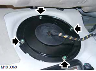
4. Turn away 4 nuts and remove the right cover of a body for access to a fuel tank.
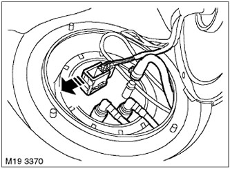
5. Disconnect the connector from the fuel priming pump.
CAUTION: The ignition must be off when disconnecting the connector.
6. Remove the central console.
CAR INTERIOR PARTS REPAIRS, Center console.
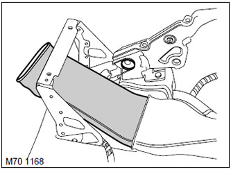
7. To access the parking brake cables, remove the middle part of the warm air supply duct to the legs of the rear passengers.
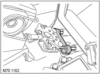
8. Remove the retaining clip from the parking brake equalizer.
9. Disconnect the parking brake cable from the equalizer.
10. Remove cardan shaft.
DRIVE SHAFTS, REPAIR WORKS, Cardan shaft - rear.
11. Disconnect the parking brake cables from the body and move them aside so that they do not interfere with further work.
12. Remove the plastic fender liner of the right rear wheel.
EXTERIOR PARTS, REPAIR WORKS, Rear wheel arch liner.
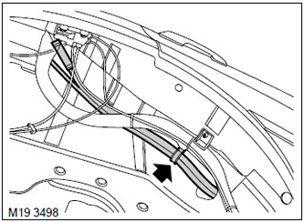
13. Loosen the filler pipe hose clamp and disconnect the hose from the filler pipe fitting.
WARNING: Fuel vapors are highly flammable, and in an enclosed area they are also toxic and explosive. There must be a fire extinguisher in the room where fuel is removed from the fuel tank (foam, carbon dioxide, gas or powder).
14. Disconnect the filler pipe hose and the fuel vapor absorber hose from the mounting bracket on the filler pipe.
15. Remove the fastening clamps from the filler pipe hose and the fuel vapor absorber hose.
16. Remove the left rear wheel.
WARNING: It is strictly forbidden to work on or under a vehicle raised only on a lift (jacking). In all cases, the car must be installed on safety stands.
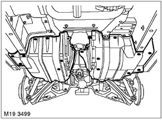
17. Turn away 16 bolts and 4 nuts fixing a protective casing of a fuel tank.
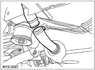
18. Loosen the clamp of the connecting hose of the filler neck.
19. Disconnect the filler pipe from the connecting hose of the filler neck.
20. Assemble all fuel tank guards.
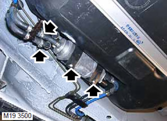
21. Remove the 2 bolts securing the auxiliary fuel priming pump to the mounting brackets, bend the mounting brackets.
22. Prepare a suitable container for draining the remaining fuel.
23. Loosen the 2 clamps and disconnect the fuel hoses from the nozzles on the rear end of the pump.
CAUTION: Before disconnecting any system elements, make sure that the places immediately adjacent to the disconnected elements are free of dirt. Immediately after disconnection, close the open ends of the pipelines with plugs to prevent foreign particles from entering the system.
24. Take the fuel priming pump aside and fix it.
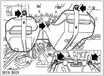
25. Together with an assistant, unscrew the 5 bolts securing the fuel tank to the body, lower and remove it from the vehicle.
NOTE: When lowering the fuel tank, the filler pipe and fuel vapor absorber hoses must be pulled out through the body opening.
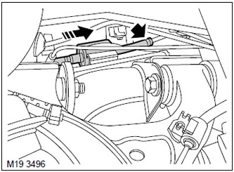
26. Remove the preheater booster pump from the rubber bracket.
27. Prepare a suitable container for draining the remaining fuel.
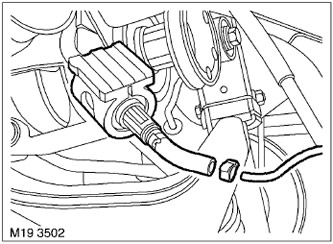
28. Loosen the clamp on the preheater pump delivery hose and disconnect the fuel hose from the pump.
NOTE: If the fuel tank was removed only to provide access to other elements of the system, then further disassembly operations should not be performed.
29. Disconnect the filler pipe hose and absorber hose from the fuel tank.
30. Remove the filler pipe hose and the fuel vapor absorber hose.
31. Remove the 4 fasteners securing the band clamps to the fuel tank. Remove the band clamps.
Installation
1. Put the filler pipe and absorber hoses on the fuel tank fittings, secure them with clamps.
2. Install band clamps on the fuel tank and secure them with fasteners.
3. Bring the fuel tank close to the vehicle.
4. Put the preheater delivery hose on the preheater fuel pump fitting and secure with a clamp.
5. Together with an assistant, install the bolts securing the fuel tank to the body and tighten them to a torque of 45 Nm (33 lb ft).
NOTE: When installing the fuel tank, it is necessary to pass the filler pipe and fuel vapor absorber hoses through the opening of the body.
6. Install and secure the preheater pump to the mounting bracket.
7. Push the inlet pipe hose onto the inlet pipe fitting and secure with a clamp.
8. Route the absorber hose along the fill pipe.
9. Connect the filler pipe to the tank filler hose and secure with a clamp.
10. Connect the fuel hoses to the auxiliary fuel priming pump and secure them with clamps.
11. Secure the fuel priming pump with the mounting bolts.
12. Install the bolts and nuts securing the fuel tank guards and tighten them to a torque of 25 Nm (18 lb ft).
13. Establish a plastic liner of the right back wheel.
EXTERIOR PARTS, REPAIR WORKS, Rear wheel arch liner.
14. Install the wheel and tighten the nuts of its fastening to 140 Nm (103 lb ft).
15. Install the cardan shaft.
DRIVE SHAFTS, REPAIR WORKS, Cardan shaft - rear.
16. Fill the fuel tank.
Td6 ENGINE FUEL SUPPLY, ADJUSTMENTS, Draining fuel from the fuel tank.
17. Reinstall the center console.
CAR INTERIOR PARTS, REPAIR WORKS, Center console.
18. Connect "mass" battery wire.
Comments on this article