Removing
WARNING: Removal and installation of the bridge requires an additional two people to support the bridge when it is lowered or moved.
1. Place stands under the front of the chassis.
2. Remove wheels.
3. Place a hydraulic jack under the axle.
4. Turn away nuts of fastening of trailing arms to a frame of the chassis.
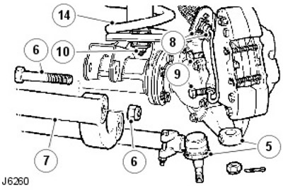
5. Disconnect the steering damper from the tie rod. Using a puller, remove the tie rod ends from the steering knuckles.
6. Turn away four nuts and turn out bolts of fastening of longitudinal levers to an arm of the bridge.
7. Remove trailing arms.
8. Turn out bolts of fastening of arms of a brake hose. Screw in the bolts to prevent oil leakage.
9. Remove the bolts from the brake calipers and tie the calipers aside.
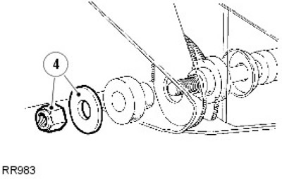
10. Turn away nuts and remove washers of fastening of shock-absorbers to a body.
11. Disconnect the tie rod from the steering knuckle arm.
12. Turn away two nuts and turn out bolts of fastening of a bar of Panhard to an arm of the bridge. Raise the bar above the bridge.
13. Put control marks on the flanges of the propeller shaft to facilitate subsequent assembly. Loosen the four nuts, remove the corresponding bolts and tie the driveshaft aside.
14. Release nipple connection type «banjo» axle vent duct and lower the axle assembly. Remove the springs.
15. Disconnect the anti-roll bar.
For more information, see chapter: Front stabilizer bar (204-01 Front suspension, Removal and installation).
16. Remove the bridge assembly.
17. Rearrange the elements to the new bridge if suitable.
Installation
1. Position the axle under the vehicle, support the left side of the axle and install the anti-roll bars.
For more information, see chapter: Front stabilizer bar (204-01 Front suspension, Removal and installation).
2. Install the cardan shaft. Tighten the bolts to 47 Nm.
3. Install the Panhard bar on the axle bracket. Tighten the bolts to 88 Nm.
4. Connect the tie rod to the steering knuckle arm. Tighten the fasteners to 40 Nm.
5. Install the shock absorbers on the bridge.
6. Install the brake calipers. Tighten the bolts to 82 Nm.
7. Tighten the upper knuckle bolts to 78 Nm.
8. Install the trailing arms on the axle brackets. Tighten the bolts to 197 Nm.
9. Connect the steering damper to the tie rod.
10. Connect the trailing arms to the chassis side members. Tighten the fasteners to 197 Nm.
11. Tighten the tie rod end to 40 Nm and install a new cotter pin.
12. Remove supports from under the chassis. Install the wheels and tighten them to the prescribed torque.
- 1. Alloy wheels - 130 Nm
- 2. Steel wheels - 100 Nm
- 3. High performance wheels - 170 Nm
Comments on this article