Contents: Removal ⇩ Installation ⇩
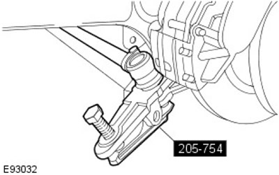
Special tool(s)
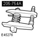 | Ball Joint Puller 205-754 (LRT-54-027) |
Removal
1.
CAUTION: Do not work on a vehicle supported solely by a jack. Be sure to place reliable supports under the vehicle.
Raise and support the vehicle.
2.
NOTE: Clean the area around the front axle fill and drain plugs.
Drain the working fluid from the front axle assembly.
- Place a container to collect the liquid.
- Remove the filler plug.
- Remove the drain plug.
3. Remove the front wheels and tires.
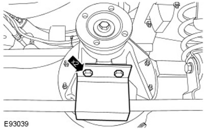
4. Remove the steering rod guard. Unscrew 2 bolts.
5.
CAUTION: Before disconnecting or removing components, clean the area around mating surfaces and connections. To prevent contamination of the system, plug all open connections.
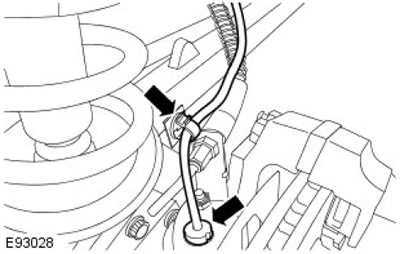
Disconnect the left front wheel speed sensor. Release the wiring harness from the clamp.
6.
CAUTION: Before disconnecting or removing components, clean the area around mating surfaces and connections. To prevent contamination of the system, plug all open connections.
Disconnect the left front brake line. To prevent fluid loss, pinch the brake hose.
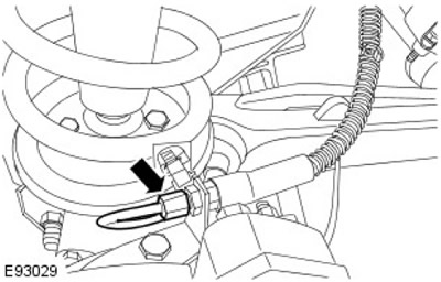
7. Release the left front brake hose. Unscrew the nut.
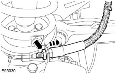
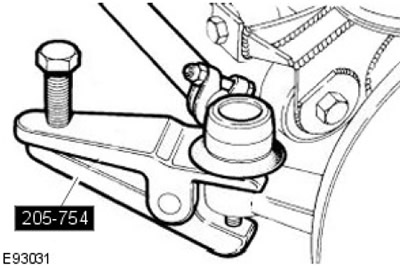
8. Using a special tool, release the tie rod end.
- Remove and discard the cotter pin.
- Unscrew the nut.
- Remove the washer.
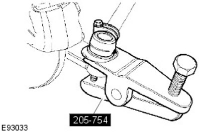
9. Disconnect the left steering rod using the special tool.
- Remove and discard the cotter pin.
- Unscrew the nut.
- Pick up the washer.
10.
CAUTION: Do not allow the pivot pin housing to hang on the axle shaft. Failure to follow this instruction may result in damage to the vehicle.
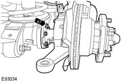
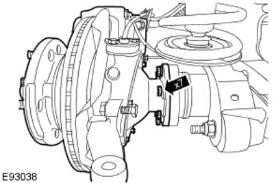
With assistance, remove the left pivot pin housing.
- Remove 7 bolts.
- Remove and discard the gasket.
11.
CAUTION: Before disconnecting or removing components, clean the area around mating surfaces and connections. To prevent contamination of the system, plug all open connections.
Disconnect the right front wheel speed sensor. Release the wiring harness from the clamp.
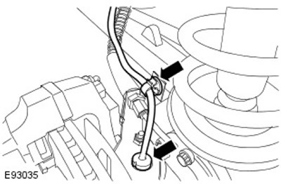
12.
CAUTION: Before disconnecting or removing components, clean the area around mating surfaces and connections. To prevent contamination of the system, plug all open connections.
Disconnect the right front brake line. To prevent fluid loss, pinch the brake hose.
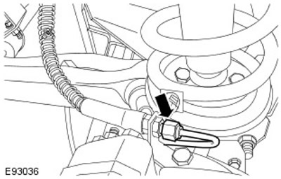
13. Release the right front brake hose. Unscrew the nut.
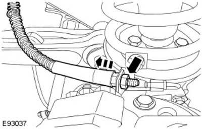
14. Using the special tool, release the right steering rod end.
- Remove and discard the cotter pin.
- Unscrew the nut.
- Remove the washer.
15.
CAUTION: Do not allow the pivot pin housing to hang on the axle shaft. Failure to follow this instruction may result in damage to the vehicle.
With assistance, remove the right hinge pin housing.
- Remove 7 bolts.
- Remove and discard the gasket.
16.
NOTE: Discard nuts.
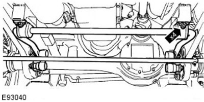
Reinstall the front anti-roll bar. Remove the 4 nuts and bolts.
17.
NOTE: Discard nuts.
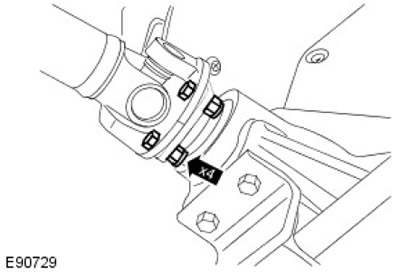
Release the front drive shaft.
- Unscrew 4 nuts and remove bolts.
- Using a suitable clamp, secure the drive shaft.
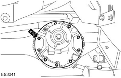
18. Remove the front differential housing. Loosen and discard the 10 nuts.
The original article is located on the website: LRman.ru
Installation
1.
NOTE: Clean the contact surfaces of the elements.
NOTE: Install new nuts.
Install the front differential housing.
- Apply a bead of the specified sealant to the mating surface of the differential housing.
- Tighten the nuts (tightening torque 41 Nm).
2.
NOTE: Install new nuts.
Secure the front drive shaft. Tighten the nuts and bolts (tightening torque 47 Nm).
3.
NOTE: Install new nuts.
Secure the front anti-roll bar. Tighten the nuts and bolts (tightening torque 68 Nm).
4.
CAUTION: When installing the pivot pin housing, support the axle shaft. Failure to follow this instruction may result in damage to the vehicle.
NOTE: Clean the contact surfaces of the elements.
With assistance, install the right hinge pin housing.
- Install a new gasket.
- Apply the prescribed sealant to the bolts.
- Tighten the bolts (tightening torque 73 Nm).
5. Secure the right steering rod end.
- Install the washer.
- Tighten the nut (tightening torque 40 Nm).
- Install a new cotter pin.
6. Secure the right front brake hose. Tighten the nut (tightening torque 10 Nm).
7.
NOTE: Remove and discard plugs.
Connect the right front brake line.
- Tighten the connection (tightening torque 15 Nm).
- Remove the hose clamp.
8.
NOTE: Remove and discard plugs.
Secure the right front wheel speed sensor. Secure the wiring harness to the clamp.
9.
CAUTION: When installing the pivot pin housing, support the axle shaft. Failure to follow this instruction may result in damage to the vehicle.
NOTE: Clean the mating surfaces of the parts.
With assistance, install the left hinge pin housing.
- Install a new gasket.
- Apply the prescribed sealant to the bolts.
- Tighten the bolts (tightening torque 73 Nm).
10. Secure the left steering rod end.
- Install the washer.
- Tighten the nut (tightening torque 40 Nm).
- Install a new cotter pin.
11. Secure the tie rod end.
- Install the washer.
- Tighten the nut (tightening torque 40 Nm).
- Install a new cotter pin.
12. Secure the left front brake hose. Tighten the nut (tightening torque 10 Nm).
13.
NOTE: Remove and discard plugs.
Connect the left front brake line.
- Tighten the connection (tightening torque 15 Nm).
- Remove the hose clamp.
14.
NOTE: Remove and discard plugs.
Secure the left front wheel speed sensor. Secure the wiring harness to the clamp.
15. Install the steering rod guard. Tighten the bolts (tightening torque 30 Nm).
16. Fill the front axle assembly with the correct amount of prescribed fluid.
- Screw in and tighten the drain plug (tightening torque 60 Nm).
- Screw in and tighten the filler plug (tightening torque 60 Nm).
- Place the container.
17. Bleed the front brakes.
For more information, refer to the chapter: Bleeding the Brake System (206-00 Brake System - General Information, General Procedures).
18. Install the front wheels with tires. Tighten the wheel nuts (tightening torque 140 Nm).
Comments on this article