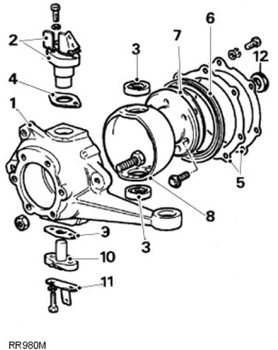
| Pos. | spare part no | Name |
| 1. | - | Rounded fist |
| 2. | - | Top kingpin and brake hose bracket |
| 3. | - | Upper and lower pivot bearings |
| 4. | - | Adjusting gasket |
| 5. | - | Lock bar and washer |
| 6. | - | Oil seal |
| 7. | - | Pad |
| 8. | - | Kingpin bearing housing |
| 9. | - | Pad |
| 10. | - | Lower king pin |
| 11. | - | Mudguard bracket |
| 12. | - | Steering knuckle inner oil seal |
Disassembly
1. Remove the front hub assembly.
For more information, see the chapter: Wheel Bearing and Wheel Hub - Vehicles Built Up To: 01/1999 (204-01, Removal and installation) / Front Wheel Bearing and Wheel Hub (204-01 Front Suspension, Removal and installation).
2.
NOTE: On later vehicles, the steering knuckle is filled with lifetime grease. Control and drain plugs are absent.
Empty the steering knuckle and replace the plug.
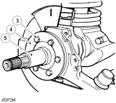
3. Turn out 6 bolts of fastening of a splined shaft of a semiaxis to a rotary fist.
4. Remove the mudguard.
5. Remove the splined axle shaft and gasket.
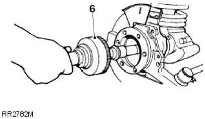
6. Remove the axle shaft and constant velocity joint from the drive axle housing.
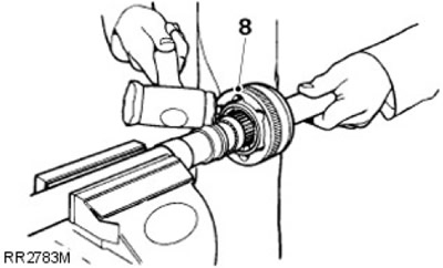
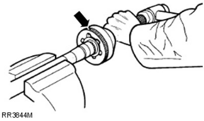
7. Clamp the axle shaft securely in a soft-jawed vise.
8. Using a soft-faced hammer, remove the CV joint from the axle shaft.
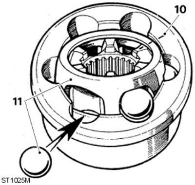
9. Remove the circlip and bushing from the axle shaft.
10. Mark the position of the CV joint, inner and outer rings, and cage for ease of assembly.
11. Rotate cage and inner ring to remove balls.
12. Inspect all components, in particular the inner and outer races, cage balls and bearing surfaces for damage and excessive wear.
13. The maximum allowable axial clearance of the assembled hinge is 0.64 mm. Replace if worn or damaged. Lubricate with recommended oil when reassembling.
Assembly
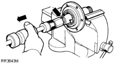
1. Install bushing and new circlip.
2. Place the CV joint onto the shaft splines and, using a soft faced hammer, fully install the CV joint.
3. Drill and cut the thrust ring with a chisel, being careful not to damage the axle shaft spline.
4. Remove bearing and oil seal using special tool LRT-37-004 and impact tool LRT-99-004. Make sure the tool lug is behind the bearing to remove it.
5. Repeat according to oil seal removal instructions.
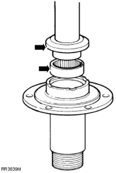
6. Lubricate the seal and lip with EP90 oil and, using the special tool LRT-54-004, install a new oil seal cavity side first.
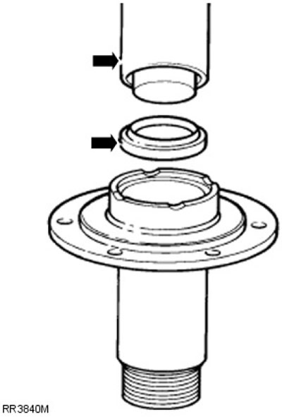
7. Using special tool LRT-54-005, install the bearing so that the part number is visible after installation. The bearing must be flush with the end surface of the splined axle shaft.
8. Press a new thrust ring onto the splined axle shaft.
9.
NOTE: Removal of the oil seal and retainer bar is possible after removal of the pivot bearing housing.
Turn out bolts of fastening of a lock lath of an oil consolidation and a lining. Remove the assembly from the steering knuckle.
10. Turn out two bolts of fastening of the lower rotary king pin to a rotary fist.
11. Remove the brake disc shield bracket.
12. Tap the tab to remove the lower kingpin and spacer.
13. Turn out two bolts of fastening of an arm of a brake hose and the top rotary kingpin.
14. Remove bracket, top pivot and shims.
15. Remove the kingpin when removing the lower and upper bearings.
16.
NOTE: Use the upper bearing hole to gain access to the lower bearing race.
Remove the lower bearing race from the pivot bearing housing.
17. Turn out 7 bolts of fastening of the case of bearings of rotary kingpins to a case of the bridge.
18. Remove the inner oil seal from the rear of the steering knuckle.
19.
NOTE: Use the lower bearing hole to access the upper bearing race.
Remove the upper bearing race from the pivot bearing housing.
20. Replace the steering knuckle if worn, corroded or damaged.
21.
CAUTION: Do not distort the bearing races when installing. Otherwise, damage may occur.
Install the upper and lower bearing races into the kingpin bearing housing.
22. Install the inner steering knuckle oil seal to the rear of the knuckle, sealing lips facing out. Lubricate the sealing lips.
23. Apply sealant, part number STC 50552, to the bolts securing the kingpin bearing housing to the drive axle housing.
24. Apply sealant to both sides of the gasket. Position the pivot bearing housing against the mating surface of the axle.
25. Install retainer bar, gasket and oil seal on axle flange in preparation for assembly.
26. Fasten the kingpin bearing housing to the axle flange with 7 bolts. Tighten to 73 Nm.
27. Lubricate and install the upper and lower kingpin tapered roller bearings.
28. Position the knuckle over the pivot bearing housing.
29. Apply sealant to both sides of the gasket and install the washer on the lower kingpin.
30. Loosely install the brake shield bracket plus lower kingpin with the protrusion outward onto the steering knuckle.
31. Loosely install the top kingpin plus existing shims and brake hose bracket onto the steering knuckle.
32. Apply sealant, part number STC 50552, to the threads of the kingpin bolts. Tighten the bolts to 25 Nm, bend the locking tabs.
33. Apply sealant, part number STC 50552, to the threads of the upper kingpin mounting bolts, screw in the bolts and tighten to 65 Nm.
34.
NOTE: The steering knuckle oil seal and axle need not be installed.
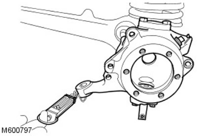
Connect a dynamometer to the tie rod ball joint hole and pull the dynamometer to determine the force required to turn the steering knuckle. The resistance after overcoming the initial inertia should be in the range from 1.16 to 1.46 kg. Adjust by removing shims or adding them to the kingpin.
35. After making the correct adjustment, remove the upper kingpin bolts. Apply sealant, part number STC 50552, to the threads of the bolts. Screw in the bolts and tighten them to 65 Nm; bend the locking tabs.
36. Apply the recommended grease between the lips of the steering knuckle oil seal.
37. Install the oil seal, gasket and retainer bar. Secure with 7 bolts using spring washers. Tighten to 10 Nm.
38. Install the tie rods and tie rods and secure with new cotter pins. Tighten the fastening element with a force of 40 Nm.
39. Install the brake disc shield.
40. Loosely install the kingpin stop bolt and nut.
41. Apply the recommended grease between the lips of the steering knuckle oil seal.
42. Secure the oil seal using the retaining bar and clamp bolts. Tighten to 10 Nm.
43. Install the tie rods and tie rods and secure with new cotter pins.
44. Loosely screw in the king pin stop bolt for later adjustment.
45. Install the brake disc shield.
46.
CAUTION: Be careful not to damage the axle shaft oil seals.
Install the axle shaft and, after engaging with the differential splines, insert the assembly completely.
47. Install a new gasket on the mating surface between the steering knuckle and the axle shaft spline. Apply sealant, part number STC 50552, to the threads of the axle spline shaft bolts.
48.
CAUTION: Before securing the wheel axle, make sure that the CV joint bearing journal is connected to the thrust ring on the axle shaft spline.
Install the axle shaft spline so that the flat is at the 12 o'clock position.
49. Establish a mudguard and by means of 6 bolts connect a splined shaft of a semiaxis to a rotary fist. Tighten the bolts evenly to 65 Nm.
50. Fix the connecting brake hoses on the appropriate bracket.
51. Install the front hub assembly.
For more information, see the chapter: Wheel Bearing and Wheel Hub - Vehicles Built Up To: 01/1999 (204-01, Removal and installation) / Front Wheel Bearing and Wheel Hub (204-01 Front Suspension, Removal and installation).
52. Check for the oil drain plug in the steering knuckle.
53. Remove the control and filler plugs from the steering knuckle.
54.
NOTE: On later vehicles, lubricate the steering knuckle with 0.33 liters of Molytex EP 00 grease.
Check the level and fill with new oil until the oil starts to flow out of the check hole. Drain excess oil and wipe the area dry.
For more information, see the chapter: Specifications (205-03 Front Drive Axle/Differential, Specifications).
55. Screw the control and filler plugs into the steering knuckle.
56. Adjust the stop bolts of the pivot pins.
For more information, see chapter: Steering Lock Stop Adjustment (211-00 Steering System -General Information, General Procedures).
Comments on this article