


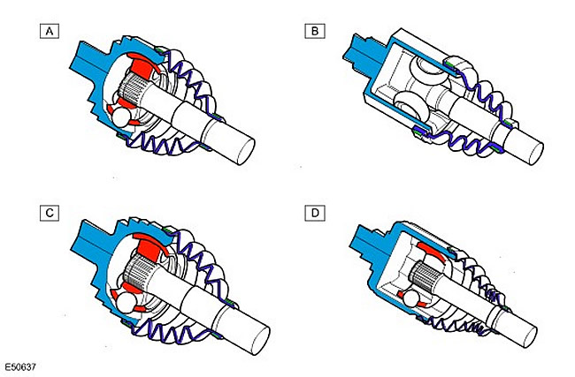
| Item name | Spare part catalog number | Description |
| A | - | Outer joint of the front axle shaft |
| B | - | Rear axle outer joint |
| C | - | Inner joint of the rear axle shaft |
| D | - | Front axle inner joint |
The outer and rear inner CV joints are Birfield joints. (constant velocity joints). This design uses elliptical grooves in which 6 steel balls are placed. The balls are additionally held by the housing. Equal angular velocities are achieved due to the position of the steel balls. If you pass an axle through the balls and the driven hub or differential shaft, the two axles will always divide each other in half at the drive angle. This allows rotation to be transmitted from the drive shaft to the driven hub or differential shaft without loss of angular velocity and regardless of the shaft angle. CV joints are filled with consistent grease, which is held in them by a synthetic rubber boot. On each side, the boot is secured with a metal clamp, which ensures a seal and does not allow moisture and dirt to penetrate the joint. CV joints are held on the corresponding shaft or pipe by an internal retaining ring. Retaining rings are located in the grooves of each shaft or at the ends of the pipes and enter the mating grooves of the CV joint.
CAUTION: In the joints of this type, the inner hub is not fixed in the joint housing. The joint remains in an unfastened state and is held only by the boot. Thus, by pulling on the shaft, the hub can be pulled out of the joint housing. For this reason, care must be taken when dismantling and installing front drive shafts.
The shaft is connected to the outer tube in a free-sliding manner, allowing for minor changes in length that occur during suspension operation. The shaft fits into a ball cage secured inside the outer tube. The ball cage provides a rigid attachment of the shaft to the outer tube, while allowing it to move freely back and forth inside the tube as needed. A sealing plug is pressed into the outer tube, holding the lubricant around the balls in the cage.
Internal CV joints have the same design and operating principle as external ones, except that they use rollers instead of balls to transmit rotational motion.
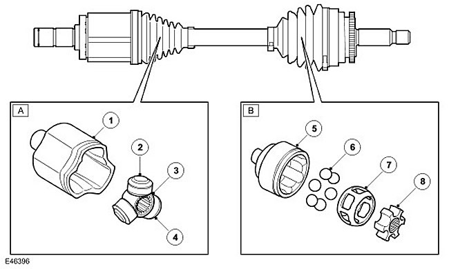
[Details can be found on the website: www.LRman.ru]
| Item name | Spare part catalog number | Description |
| A | - | Inner CV joint |
| B | - | Outer CV joint |
| 1 | - | Tulip shaped outer ring |
| 2 | - | Trunnions (3 pcs.) |
| 3 | - | Crosspiece |
| 4 | - | Rollers (3 pcs.) |
| 5 | - | Outer ring |
| 6 | - | Steel balls (6 pcs.) |
| 7 | - | Housing (separator) |
| 8 | - | Inner ring |
The front inner joint is a tripod joint. Torque is transmitted from the outer ring to the connecting shaft by means of rollers rotating on bearing needles around the journals of the tripod joint crosspiece. Roller tracks in the outer ring allow the tripod joint to move at an angle and along the axis inside the joint.
The inner CV joint shaft has splines that engage with the splines of the front differential. This type of joint does not have an internal locking mechanism, so care must be taken when servicing, otherwise the shaft and CV joint may separate from each other.
Comments on this article