


Contents: Removal ⇩ Installation ⇩
Special tool
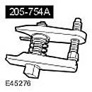 Ball Joint Puller 205-754 (LRT-54-027)
 | 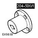 Device for dismantling/replacing half-shafts 204-506/1 (LRT-60-030/1)
 | 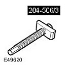 Device for dismantling/replacing half-shafts 204-506/3 (LRT-60-030/3)
 |
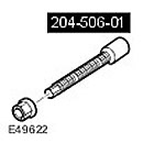 Device for dismantling/replacing half-shafts 204-506-01
 | 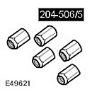 Holders - device for dismantling/replacing axle shafts 204-506/5 (LRT-60-030/5)
 | 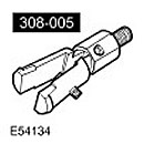 Tool for removing the drive axle seal 308-005 (LRT-37-004/2)
 |
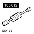 Pulse extractor 100-012 (LRT-99-004)
 | 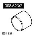 Mounting tool/guide for axle shaft seal 308-626/2
 | 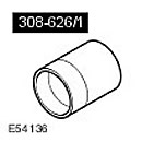 Device for mounting axle shaft seal 308-626/1
 |
Removal
CAUTION: To avoid damage to the ball joint, do not store or install the axle shafts in the fully folded position.
CAUTION: To avoid damage to the ball joint, do not allow the axle shaft to hang loose on one side.
CAUTION: AAR type roller joints (Angularly Adjusted Roller), mounted on the inside of some axle shafts, do not have an internal retaining mechanism and can therefore become separated.
1.
CAUTION: Never work on a vehicle supported only by a jack. Always support the vehicle with special stands.
Raise and support the vehicle.
2. Drain the differential. For more information, refer to Draining and Filling Differential Transmission Fluid (54.15.02)
3. Remove the wheel.
4. Loosen the axle shaft mounting nut. Discard the nut.
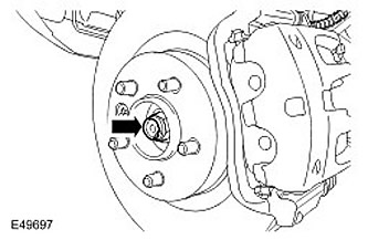
5.
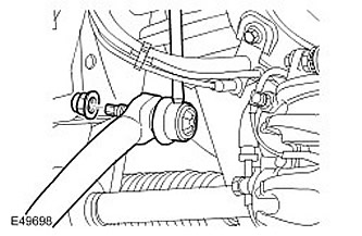
CAUTION: Use the included Allen key to prevent the ball joint from turning.
Disconnect the right stabilizer bar. Unscrew and discard the nut.
6.
CAUTION: Use the included Allen key to prevent the ball joint from turning.
Loosen the stabilizer bar mounting nut. Loosen and discard the nut.
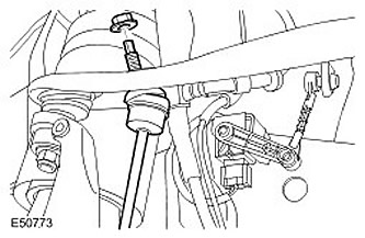
7. Disconnect the brake hose mounting bracket from the wheel knuckle. Remove the bolt.
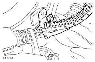
8. Loosen the nut securing the ball joint to the steering rod.
9.
CAUTION: Make sure the protective cover is not damaged. Damage to the protective hinge will result in premature failure of the hinge.
Using a special tool, disconnect the ball joint of the steering rod from the steering knuckle. Discard the nut.
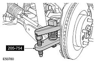
10.
CAUTION: To prevent the steering knuckle from falling forward and separating the inner axle joint, support the steering knuckle.
Loosen the upper control arm mounting nut.
11.
CAUTION: Make sure the protective cover is not damaged. Damage to the protective cover will result in premature failure of the hinge.
Using a special tool, disconnect the upper control arm ball joint. Remove the nut and discard it.
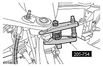
12.
CAUTION: Excessive deflection may damage the lower control arm ball joint. The steering knuckle must be supported at all times. Do not allow the steering knuckle to hang on the lower control arm. Failure to follow this instruction may result in vehicle damage.
Using special tools, disconnect the axle shaft from the wheel hub.
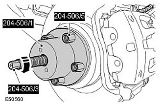
13. Disconnect the axle shaft from the steering knuckle.
14. Remove the axle shaft from the differential housing.
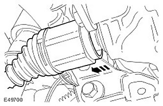
15. Remove the axle shaft.
- Raise the stabilizer bar so that the axle shaft can be removed.
- Remove the snap ring and discard it.
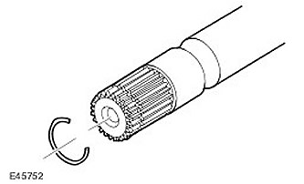
16. Using special tools, remove the axle shaft seal and discard it.

Installation
1. Clean the parts.
2. Using the special tools, install the new axle shaft seal. Do not open the axle shaft seal guard until the axle shaft is fully seated.
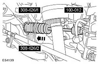
3.
NOTE: Do not fully insert the axle shaft until the oil seal protector has been removed.
Install the axle shaft.
- Install the retaining ring.
- Lubricate the seal and bearing surfaces with clean gear oil.
- Make sure the snap ring is fully seated and holds the axle shaft in place.
- Open the axle shaft seal protection.
The publication was copied from a web resource (LRMAN.RU)
4.
NOTE: The axle shaft seal guard should separate into two pieces.
Remove and discard the axle shaft seal guard.
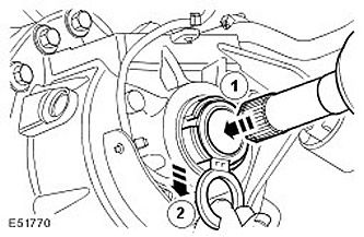
5.
CAUTION: Excessive deflection may damage the lower control arm ball joint. The steering knuckle must be supported at all times. Do not allow the steering knuckle to hang on the lower control arm. Failure to follow this instruction may result in vehicle damage.
Using special tools, install the axle shaft into the wheel hub.
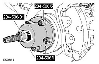
6. Attach the upper control arm to the wheel knuckle. Screw on a new nut and tighten it. (tightening torque 70 Nm).
7. Secure the stabilizer bar. Screw on a new nut and tighten it. (tightening torque 115 Nm).
8. Attach the ball joint of the steering rod. Screw on a new nut and tighten it (tightening torque 76 Nm).
9. Install the new axle shaft nut and tighten it lightly.
10. Secure the brake hose mounting bracket to the steering knuckle. Tighten the bolt. (tightening torque 22 Nm).
11. Secure the right stabilizer bar. Screw on a new nut and tighten it. (tightening torque 115 Nm).
12. Tighten the new axle shaft nut. (tightening torque 350 Nm). Secure the nut to the axle shaft.
13. Install the wheels. Tighten the wheel nuts. (tightening torque 140 Nm).
14.
CAUTION: Do not fill the differential with oil up to the filler plug hole. The filler plug hole is used only to fill the differential with oil and is not intended to serve as a level indicator.
Fill the differential with the required amount of oil. For more information, refer to Draining and Filling Differential with Transmission Oil (54.15.02)
Comments on this article