


Contents: Dismantling ⇩ Assembly ⇩
Dismantling
1. Raise the front of the vehicle.
CAUTION: Do not work under a vehicle supported solely by a jack or lift. Always support the vehicle with safety stands.
2. Remove the front left wheel.
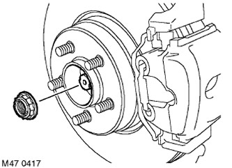
3. Release the wheel hub nut retainer.
4. With an assistant pressing the brake pedal, remove and discard the wheel hub nut.
5. Remove the brake disc.
BRAKE SYSTEM, REPAIR WORK, Brake disc - front brake mechanisms.
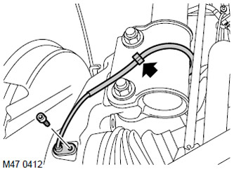
6. Release the wheel speed sensor cable from the retainer.
7. Release the cable from the retainer on the shock absorber, remove the Allen screw and remove the wheel speed sensor from the wheel bearing support.
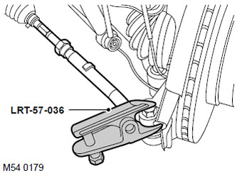
8. Remove and discard the nut securing the left ball joint to the steering knuckle.
9. Screw the M14 nut onto the end of the ball joint flush with the end of the threaded part of the joint.
10. Using the LRT-57-036 tool, separate the ball pin from the steering knuckle. Remove the M14 nut and pull the ball pin out of the steering knuckle.
CAUTION: Make sure that the ball joint boot is not damaged. A damaged boot will cause the ball joint to fail.
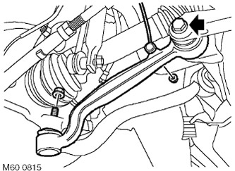
11. Loosen the nut securing the vertical body position sensor rod to the lower arm and release the rod.
CAUTION: Hold the ball joint from turning using an open-end wrench placed on the flat grooves.
12. Loosen the bolt securing the lower arm to the subframe by a quarter of a turn.
13. Remove the nut securing the lower arm ball joint to the wheel bearing support.
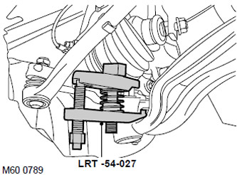
14. Using the LRT-54-027 tool, release the lower arm ball joint and separate the lower arm from the wheel bearing support.
CAUTION: Make sure that the ball joint boot is not damaged. A damaged boot will cause the ball joint to fail.
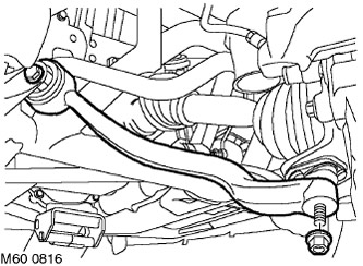
15. Loosen the tie rod to subframe mounting bolt by a quarter of a turn.
16. Unscrew the nut securing the rod to the ball joint.
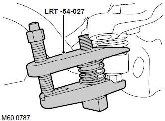
17. Using the LRT-54-027 tool, separate the tie rod from the ball joint.
CAUTION: Make sure that the ball joint boot is not damaged. A damaged boot will cause the ball joint to fail.
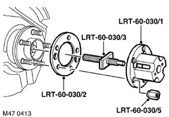
18. Install the central screw LRT-60-030/3 into the device LRT-60-030/1 and connect it to the hub through the intermediate flange LRT-60-030/2. Secure the connection with the nut LRT-60-030/5.
19. Tighten the center screw to press the drive shaft out of the wheel hub.
20. Remove the devices.
21. Place a container to collect any leaking oil.
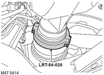
22. Install the LRT-54-026 tool onto the drive shaft inner joint.
23. Separate the drive shaft from the differential using levers.
24. Release the drive shaft from the hub.
25. Remove the drive shaft assembly and keep it horizontal to avoid damaging the differential seal.
26. Remove and discard the drive shaft retaining ring.
Assembly
1. Wipe the end of the drive shaft and the differential bushing.
2. Install a new snap ring onto the end of the drive shaft.
3. Lubricate the seal lips with clean transmission oil.
FILLING CAPACITIES, USED OPERATING LIQUIDS, OILS AND SEALANTS, Lubrication system.
4. Install the end of the drive shaft into the differential, ensuring that the retaining ring is fully engaged.
CAUTION: Press down on the drive shaft to ensure that the snap ring is seated in its groove and holds the shaft.
5. Clean the drive shaft and hub splines from dirt.
6. Apply a small amount of grease to the splines and the surface that contacts the sealing ring.
FILLING CAPACITIES, USED OPERATING LIQUIDS, OILS AND SEALANTS, Lubrication system.
7. Place the end of the drive shaft into the hub.
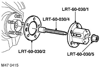
8. Install the LRT-60-030/4 tool onto the drive shaft.
9. Install the LRT-60-030/1 fixture with the LRT-60-030/2 intermediate flange and secure with the LRT-60-030/5 nut.
10. Screw the nut onto the LRT-60-030/4 tool and, while tightening the nut, press the drive shaft into the hub.
11. Remove the devices.
12. Clean the conical surfaces of the ball joints and the sockets for their installation from dirt.
13. Connect the rod to the ball joint, install a new mounting nut and tighten it to a torque of 80 N·m.
14. Attach the lower arm ball joint to the wheel bearing support, screw on the mounting nut and tighten it to a torque of 80 N·m.
15. Connect the vertical body position sensor rod to the lower arm and tighten the mounting nut to a torque of 8 N·m.
CAUTION: Make sure the sensor lever is facing outward.
16. Connect the ball joint pin to the steering knuckle, install a new nut and tighten it to a torque of 80 N·m.
17. Clean the surface of the wheel speed sensor, apply anti-seize lubricant to the sensor, and install it on the wheel bearing support.
FILLING CAPACITIES, USED OPERATING LIQUIDS, OILS AND SEALANTS, Lubrication system.
18. Install the Allen type screw for the wheel speed sensor and tighten the screw to 8 N·m.
19. Secure the sensor cable to the shock absorber.
20. Install the brake disc.
BRAKE SYSTEM, REPAIR WORK, Brake disc - front brake mechanisms.
21. Install the new hub nut and tighten the nut to 420 Nm.
22. Lock the nut on the end of the drive shaft.
23. Replace the wheel and tighten the nuts to a torque of 140 Nm.
24. Remove the supports and lower the vehicle.
25. Install the new lower arm-to-subframe mounting bolt, tighten it to 165 Nm, then tighten it another 90°.
26. Tighten the new tie rod to subframe mounting bolt to 165 Nm, then tighten it another 90°.
27.
CAUTION: Nuts and bolts should be tightened with the vehicle's wheels normally on the ground.
28. Add oil to the front axle final drive housing.
FRONT AXLE MAIN GEAR AND DIFFERENTIAL, ADJUSTMENTS, Front main gear and differential housing - oil drain and filling.
29. Check the front wheel alignment.
STEERING, ADJUSTMENTS, Front wheel alignment angles - checking and adjustment.
Comments on this article