car logo Ford
car logo Volkswagen
car logo BMW
car logo Opel
car logo Audi
car logo Toyota
car logo Peugeot
English Русский
Български
Беларускі
Український
Српски
Hrvatski
Română
Polski
Slovenský
Magyar


Main
Freelander
Discovery
Range Rover
Defender
Contacts
Articles

Upper arm rear suspension (Defender 2007+)

 
  • Main
  • Defender
  • Defender 2007+
  • Chassis
  • Car suspension
  • Upper arm rear suspension
 
        0  
Contents: Removal ⇩ Installation ⇩

Removal


1. Place supports under the rear of the chassis so that the axle hangs freely.

2. Remove the upper arm bracket fasteners from the frame.

3. Remove the upper control arm fastenings from the support bracket.
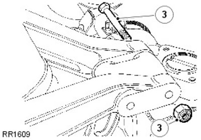
3. Remove the upper control arm fastenings from the support bracket.


4. Remove the upper arm assembly with the frame bracket.

5. Remove the bolt.

6. Separate the upper arm from the bracket.

6. Separate the upper arm from the bracket.


7. Replace the bushing.

8. Press out the rubber bushings.

9.
CAUTION: Apply force to the outer edge of the bushing, not the inner rubber portion.


Center the bushing in the housing.

Installation


1.
NOTE: Do not fully tighten fasteners until all fasteners are in place.


Attach the upper control arm to the frame bracket.

2. Connect the upper arm to the pivot bracket and tighten the fasteners to 115 Nm.


3. Install the frame bracket to the chassis support.

4. If you are threading a new nut onto the upper control arm bolt, tighten it fully to 115 Nm. If you are threading the existing nut, tighten it to 176 Nm.


This article is available at russian, bulgarian, belarusian, ukrainian, serbian, croatian, romanian, polish, slovak, hungarian
Article review: Saveliy Ushakov


Previous articles
Suspension specification
Adjusting the front wheel alignment
Rear air shock absorber
Rear shock absorber

Current article
Upper arm rear suspension

Next articles
Rear anti-roll bar rear suspension
Description and operating principle of the rear suspension
Lower arm rear suspension
Rear suspension dynamic deflection limiter
Wheel bearing and wheel hub rear suspension
Rear suspension spring
Rear stabilizer bar
Rear suspension wheel studs


Similar articles from Land Rover repair manuals:
• Description and operating principle of the rear suspension Freelander 2 (2006-2014)
• Rear Suspension Specification Freelander 1 (1997-2006)
• Rear Suspension Specification Discovery 3 (2004-2009)
• Rear suspension — device Discovery 1 (1989-1998)
• Front and rear suspension Range Rover 3 (2001-2012)

Comments on this article


No comments yet


How much will 34 + 19 =


Defender 2007+ 
  • General information
  • Maintenance
  • Identification codes
  • Power unit
  • Diesel engine ID4 2.4L
  • Engine inspection
  • Engine cooling
  • Fuel supply
  • Fuel tank
  • Exhaust system
  • Accessory drive
  • Air filtration
  • Electronic parts
  • Mechanical gearbox
  • Transfer case
  • Clutch
  • Chassis
  • Car suspension
  • Wheels and tires
  • Steering
  • Steering column
  • Brake system
  • Front drive axle
  • Rear drive axle
  • Cardan shaft
  • Body and coating
  • Interior trim
  • Instrument panel and console
  • Exterior finish
  • Lockable body parts
  • Handles, locks, latches
  • Glass, frames and mechanisms
  • Windshield wipers and washers
  • Seats
  • Electrical equipment
  • Battery
  • Generator and regulator
  • Lighting and headlights
  • Winch
  • Heating and ventilation
  • Instrument panel
  • Other electronics


LRman.ru © 2013-2026 | Mobile version | Free Lander | Discovery | Range Rover | Defender | Contacts | | Sitemap |
Car repair and service instructions Land Rover: Freelander, Discovery, Range Rover, Defender
We use cookies to make pages load faster and provide a more user-friendly experience 🍪