Contents: Arrangement of elements ⇩ Review ⇩ Spring and shock absorber ⇩ Transverse steering rods ⇩ Longitudinal steering rod ⇩ Wheel knuckle and hub ⇩ Anti-roll bar ⇩
Arrangement of elements
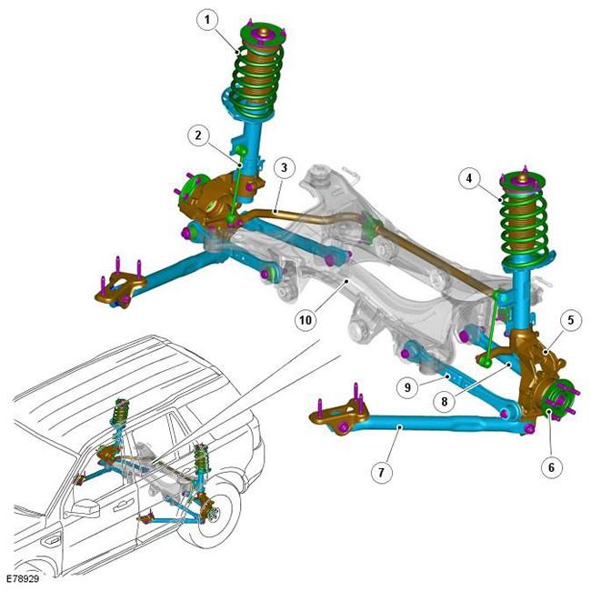
| Pos. | Spare part number | Name |
| 1 | - | Right (RH) spring and shock absorber assembly |
| 2 | - | Stabilizer link |
| 3 | - | Anti-roll bar |
| 4 | - | Left (LH) spring and shock absorber assembly |
| 5 | - | Wheel cam |
| 6 | - | Hub |
| 7 | - | Longitudinal steering rod |
| 8 | - | Rear tie rod |
| 9 | - | Front tie rod |
| 10 | - | Stretcher |
Review
The rear suspension uses long-travel MacPherson struts to optimize dynamic performance on and off-road.
The suspension elements are mounted on a subframe, which forms a rigid platform attached to the bottom of the car body. The subframe is mounted on the body on four bushings with variable compression coefficients to absorb lateral and longitudinal loads when cornering and braking.
Spring and shock absorber
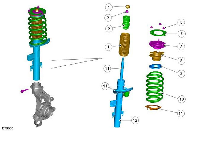
| Pos. | Spare part number | Name |
| 1 | - | Rubber cuff |
| 2 | - | Auxiliary device of elastic element |
| 3 | - | Lock-nut |
| 4 | - | Lid |
| 5 | - | Locknut (3 pcs.) |
| 6 | - | Pad |
| 7 | - | Upper support assembly |
| 8 | - | Remote element |
| 9 | - | Spring insulator |
| 10 | - | Spring |
| 11 | - | Spring insulator |
| 12 | - | Shock absorber housing |
| 13 | - | Spring seat |
| 14 | - | Shock absorber piston rod |
The spring and shock absorber assembly is a twin-tube design, with a traditional coil spring located on a welded spring seat on the shock absorber tube. The lower end of the shock absorber body is located in the wheel knuckle, which is secured with a bolt.
The damping capacity of the shock absorber is determined by limiting the flow of the working fluid through the internal channels of the shock absorber. The shock absorber rod moves along the axis of the working cylinder, and due to the resistance to the flow of liquid, forces are created that prevent the relative movement of the rod and the working cylinder. These forces cause the damping of vibrations that occur when the car moves over uneven roads. A seal is installed between the rod and the working cylinder of the shock absorber, which, on the one hand, does not allow the working fluid to leak out, and on the other hand, prevents dirt and moisture from entering the shock absorber. In addition, the seal plays the role of a rod cleaner.
The shock absorber rod passes through the central hole of the upper support assembly. The outer end of the rod is threaded. A self-locking nut secures the shock absorber rod to the upper support. An auxiliary device of the elastic element is installed on the shock absorber rod. It prevents contact of the upper support with the upper part of the shock absorber when the suspension is fully compressed, and also helps to adjust the suspension. A rubber cuff is installed between the shock absorber body and the upper support; it protects the shock absorber piston rod from damage.
The spring installed depends on the vehicle specification. Each spring is color coded to indicate its rating and installation conditions.
The spring is located in the spring seat, which is an integral part of the shock absorber body and includes a spring insulator. The spring seat design does not allow the spring to rotate. The spring has a linear compression ratio and is inclined to counteract the forces acting during cornering. The opposite end of the spring is also located in the spring insulator, which is installed in the upper support assembly. Both spring insulators are made of rubber and prevent the transmission of noise to the car body that occurs when the shock absorber and spring are stretched/compressed. A shock-absorbing weight is attached to the shock absorber spring seat, designed to absorb vibrations and prevent noise from penetrating into the car interior.
The top support has a gasket that prevents moisture from getting between the support and the mount. The top support is secured to the reinforced dome of the rack on the chassis with 3 built-in studs and self-locking nuts.
Two brackets are welded to the shock absorber body. One bracket provides the stabilizer strut mount. The second bracket provides the brake hose and wheel speed sensor wire mount. This bracket also geometrically locks the shock absorber into the wheel knuckle and its position is extremely important for controlling the height of the car body trim.
Transverse steering rods
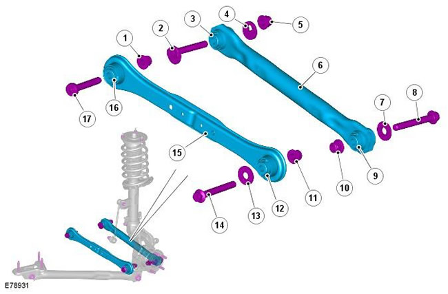
| Pos. | Spare part number | Name |
| 1 | - | Lock-nut |
| 2 | - | Eccentric bolt |
| 3 | - | Inner sleeve |
| 4 | - | Eccentric cam washer |
| 5 | - | Lock-nut |
| 6 | - | Rear tie rod |
| 7 | - | Washer |
| 8 | - | Bolt |
| 9 | - | Outer bushing |
| 10 | - | Lock-nut |
| 11 | - | Lock-nut |
| 12 | - | Outer bushing |
| 13 | - | Washer |
| 14 | - | Bolt |
| 15 | - | Front tie rod |
| 16 | - | Inner sleeve |
| 17 | - | Bolt |
The lateral position of the wheel is controlled by 2 transverse steering rods located between the subframe and the wheel knuckle. The rods are made long to ensure perfect camber control. Each steering rod is equipped with dynamic bushings that control the camber of the rear wheels, progressively changing it as the cornering load increases, resulting in limited passive steering of the rear wheels. The 2 transverse steering rods have different designs. The front rod is made of stamped steel. The rear rod is made of pressed and cut tube. The rods are designed to withstand the lifting loads of the car.
The front transverse rod has bushings that are compressed under the forces acting during cornering, which, in addition to controlling the camber, ensures controlled toe-in of the rear wheels. In the middle of the front rod is a deformation point. It allows the rod to deform in the event of a serious side impact of the rear wheel, for example, when hitting a curb. In the event of a serious side impact, the rod deforms, absorbing the impact energy and protecting the subframe from damage. The degree of deformation leads to the formation of excessive toe-in, which is immediately noticeable to the driver.
The rear transverse rod is attached to the subframe using an eccentric bolt and washer, which allows for adjustment of the wheel alignment angle.
Both tie rods are secured to the subframe with bolts and lock nuts. The outer ends of each tie rod are located in mounting holes built into the wheel knuckle and secured with bolts and lock nuts.
Longitudinal steering rod
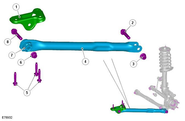
(The material was taken from a website: www.LRman.ru)
| Pos. | Spare part number | Name |
| 1 | - | Body mounting bracket |
| 2 | - | Bolt |
| 3 | - | Lock-nut |
| 4 | - | Longitudinal steering rod |
| 5 | - | Bolts |
| 6 | - | Lock-nut |
| 7 | - | Sleeve |
| 8 | - | Bolt |
The tie rods are made from pressed and cut pipe and are located between the wheel knuckle and the car body. The tie rods control the rear suspension, reacting to braking and traction forces.
The rear mount is fork-shaped and is located on each side of the bushing pressed into the wheel knuckle. The rod is secured with a bolt and lock nut passing through the bushing.
The front tie rod mount is located in a bracket that is screwed to the lower side of the car body sill. The rod is equipped with a bushing that is installed in the bracket and secured with a bolt and lock nut.
Wheel knuckle and hub
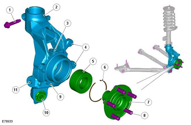
| Pos. | Spare part number | Name |
| 1 | - | Clamp bolt |
| 2 | - | Wheel cam |
| 3 | - | Anti-lock Brake System (ABS) Wheel Speed Sensor |
| 4 | - | Brake caliper mount |
| 5 | - | Bearing |
| 6 | - | Retaining ring |
| 7 | - | Hub |
| 8 | - | Hairpins |
| 9 | - | Disc shield mounting |
| 10 | - | Tie rod bushing |
| 11 | - | Front Tie Rod Fastening |
The cast steel wheel knuckle provides mounting for the tie rods, track rod, spring and shock absorber assembly, hub and wheel bearing assembly.
The extended lower projection on the knuckle has a pressed bushing and provides the attachment of the longitudinal steering rod. The rod is attached to the knuckle using a bolt with a lock nut passing through the rod and bushing.
Two additional projections on the inner surface of the wheel knuckle provide fastening of the front and rear transverse tie rods, each of which is secured with a bolt and lock nut.
The upper part of the wheel knuckle has a mounting hole for the shock absorber housing. The shock absorber housing enters the hole and is located opposite the stop on the shock absorber housing. The rear surface of the hole has a slot and allows you to fix the shock absorber housing in the wheel knuckle using a clamping bolt.
There are places for installing the brake caliper and brake disc shield. The upper surface of the wheel knuckle has a hole for installing the ABS wheel speed sensor, which is secured with a bolt.
The wheel hub assembly includes the wheel bearing and the ABS sensor pulse ring. The hub assembly is a non-serviceable element and requires replacement as a single unit.
Anti-roll bar
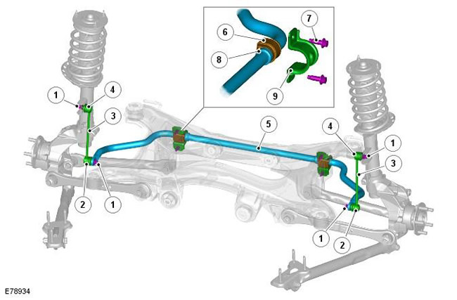
| Pos. | Spare part number | Name |
| 1 | - | Lock-nut |
| 2 | - | Ball joint |
| 3 | - | Rack |
| 4 | - | Ball joint |
| 5 | - | Anti-roll bar |
| 6 | - | Sleeve |
| 7 | - | Bolt |
| 8 | - | Ring |
| 9 | - | Clamp |
The anti-roll bar is secured to the subframe with bushings and mounting brackets. The stamped steel brackets are located above the bushings and are secured to the crossmember with bolts that are screwed into threaded holes in the subframe. The stabilizer bar has "thrust" rings pressed into the inner side of the bushings. The rings prevent lateral displacement of the stabilizer bar.
The stabilizer is made from a 22mm diameter manganese steel rod. The ends of the stabilizer are bent forward to attach to the ball joint on the stabilizer strut. Each stabilizer strut is secured with a lock nut to a bracket on the shock absorber body. The struts do not differ in the installation side and allow the stabilizer bar to move with the wheel travel, providing maximum efficiency. The stabilizer bushings are compressed type bushings that grip the stabilizer when compressed by clamps.
The stabilizer bar bushings are compression type bushings that grip the stabilizer bar when compressed by the mounting brackets. When replacing the bushings on the stabilizer bar, it is necessary to ensure that the bushings are correctly oriented in relation to the stabilizer bar. Incorrect bushing adjustment can result in excessive preload (twisting) in the bushings when the suspension is set to the nominal height position.
Comments on this article