Special tool
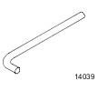 204-159 Lever, Wheel Knuckle 204-159 Lever, Wheel Knuckle | 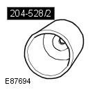 204-528/2 Remover/Installer, Bushing 204-528/2 Remover/Installer, Bushing | 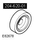 204-620-01 Installer, Wheel Knuckle Bushing 204-620-01 Installer, Wheel Knuckle Bushing |
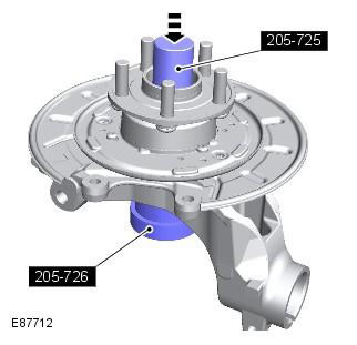
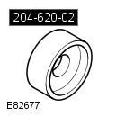 204-620-02 Remover/Installer, Wheel Knuckle Bushing 204-620-02 Remover/Installer, Wheel Knuckle Bushing | 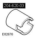 204-620-03 Remover, Wheel Knuckle Bushing 204-620-03 Remover, Wheel Knuckle Bushing | 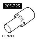 205-725 Remover/Installer, Wheel Hub 205-725 Remover/Installer, Wheel Hub |
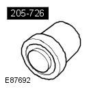 205-726 Remover/Installer, Wheel Hub Bearing 205-726 Remover/Installer, Wheel Hub Bearing | 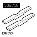 205-728 Remover/Installer, Wheel Hub 205-728 Remover/Installer, Wheel Hub | 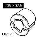 205-802/5 Remover, Wheel Hub/Bearing 205-802/5 Remover, Wheel Hub/Bearing |
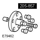 205-857 Remover, Halfshaft 205-857 Remover, Halfshaft | 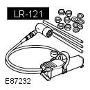 LR-121 Hydraulic Cylinder 10t LR-121 Hydraulic Cylinder 10t |
Removing
1. Raise and support the vehicle.
WARNING: Place secure stands under the vehicle.
2. Remove the wheel and tire assembly. Refer to procedure: Wheel and tire (204-04 Wheels and tires, Removal and installation).
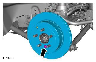
3. Loosen and discard the rear axle nut.
CAUTION: Do not use a hammer to separate the axle shaft from the hub assembly, failure to do so may result in damage to the axle shaft.
4.
CAUTION: Discard nut.
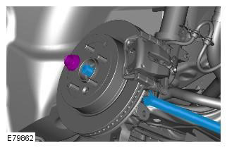
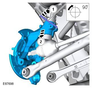
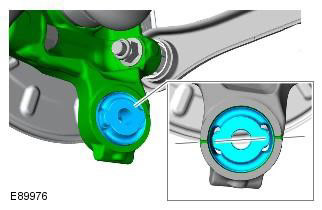
NOTE: The illustration shows the right side, the left side looks the same.
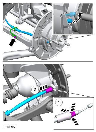
5. Disconnect the wheel speed sensor from the wheel knuckle.
6. Set aside and tie the brake caliper assembly to the support bracket.
CAUTION: Do not stress the brake hose.
7. Release the parking brake shoe adjuster.
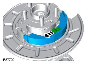
8. Remove the brake disc.
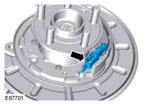
9. Disconnect the parking brake cable from the wheel knuckle. Pick up a clip.
10.
11.
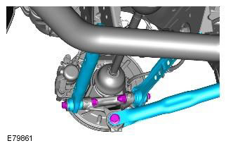
- Disconnect the rear axle. Special tool (s): 205-857
- Take aside and tie the rear axle shaft.
To avoid damage to the ball joint, do not allow the axle shaft to hang unsecured on one side.
To avoid damage to the ball joint, do not store or install the axle shafts in the maximum stowed position.
Roller joints type AAR (Angularly Adjusted Roller), mounted on the inside of some axle shafts, do not have an internal retaining mechanism and therefore may come apart.
12. Remove and discard the wheel knuckle clamp bolt.
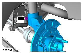
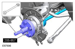
13. With assistance, remove the wheel knuckle assembly. Special tool (s): 204-159
14.
NOTE: Do not proceed with further dismantling if the element is removed only for access.
15.
16.
17.
18.
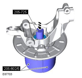
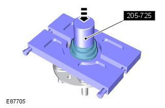
- Install the wheel knuckle assembly in the press and support with the special tool. Special tool (s): 205-802/5
- Using the special tool, press the drive flange out of the wheel knuckle assembly. Special tool (s): 205-725
NOTE: This operation will inevitably damage the bearing.
19.
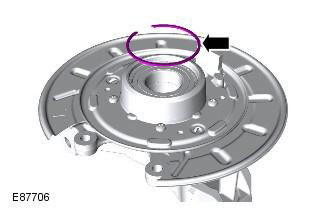
NOTE: The inner race of the bearing will remain on the drive flange.
20.
- Close both halves of a suitable bearing cage around the inner race of the bearing and install the drive flange in the press.
- Using the special tool, press the drive flange out of the inner race of the bearing. Special tool (s): 205-725
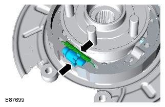
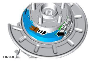
21. Remove the circlip from the wheel knuckle assembly.
22.
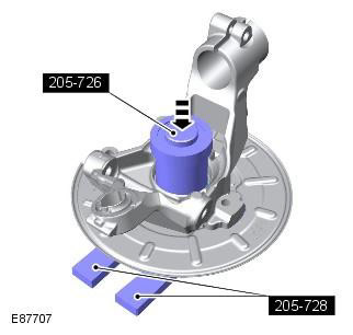
- Install the wheel knuckle assembly in the press and support with the special tools. Special tool (s): 205-728
- Using the special tool, press the wheel bearing out of the wheel knuckle assembly. Special tool (s): 205-726
23. Remove the brake base plate.
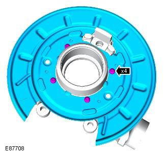
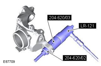
24. Remove the wheel knuckle bushing. Special tool (s): LR-121, 204-620-02, 204-620-03
CAUTION: Mark the position of the elements to facilitate subsequent installation.
Installation
1.
CAUTION: The alignment marks must be centered.
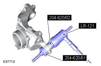
2. Install the wheel knuckle bushing. Special tool (s): LR-121, 204-620-01, 204-620-02
CAUTION: Be sure to use the correct special tool to set the bushings to the correct depth.
3. Install the brake base plate.
4.
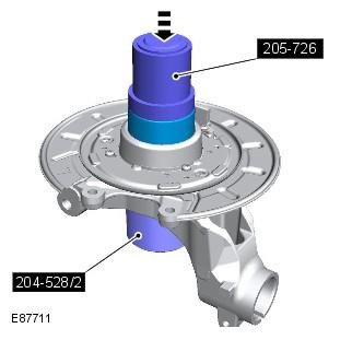
- Install the wheel knuckle assembly in the press and support with the special tool. Special tool (s): 204-528/2
- Using the special tool, press the new wheel bearing into the wheel knuckle assembly. Special tool (s): 205-726
CAUTION: One side of the bearing is magnetic. The magnetic side can be identified by the black matte finish. The magnetic side must be directed towards the inside of the vehicle. Before installing the bearing, clean the magnetic side. The bearing must be handled with the utmost care.
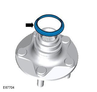
5. Install the retaining ring on the wheel knuckle assembly.
6.
- Install the wheel knuckle assembly in the press and support with the special tool. Special tool (s): 205-726
- Using the special tool, press the drive flange into the wheel knuckle assembly. Special tool (s): 205-725
7. Clean support plate and apply lubricant to surfaces in contact with brake pads.
WARNING: Do not use compressed air to clean brake parts. Dust from friction materials is harmful when it enters the lungs.
8. Clean the adjuster and set the minimum length.
9. Install the secondary brake shoe. Install the spring retainer and pin.
10.
- Install the adjusting plate and spring.
- Install the primary brake pad.
- Install the return spring.
- Install the spring retainer and pin.
WARNING: The return spring and adjusting spring must be correctly installed on the primary shoe.
CAUTION: The brake shoe spring must not be overstretched.
11. Install the brake shoe adjuster.
CAUTION: The brake shoe spring must not be overstretched.
12. With assistance, install the wheel knuckle assembly. Special tool (s): 204-159
13. Screw in a new clamping bolt of a knuckle of a wheel. Tightening torque: 110 Nm
14. Install the rear axle shaft on the drive flange.
15. Fit a new rear axle nut. Do not fully tighten at this stage.
CAUTION: Tighten the nuts finger tight only at this stage.
16. Connect both lower arms to the hub assembly. Do not fully tighten at this stage.
CAUTION: Tighten the nuts finger tight only at this stage.
17. Connect the trailing arm to the hub assembly. Do not fully tighten at this stage.
CAUTION: Tighten the nuts finger tight only at this stage.
18. Attach the parking brake cable. Attach the parking brake cable.
CAUTION: Make sure the clip is properly installed.
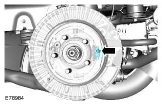
19. Install the brake disc. Tightening torque: 35 Nm
CAUTION: Clean mating surfaces of foreign material.
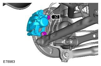
20. Attach the brake caliper and base plate to the wheel knuckle. Tightening torque: 110 Nm
Clean mating surfaces of foreign material. Make sure the brake hose is not kinked and is properly installed.
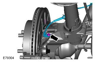
21. Install the rear wheel speed sensor on the wheel knuckle. Tightening torque: 5 Nm
22. Install the brake line and wheel speed sensor brackets. Tightening torque: 10 Nm
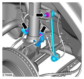
23. Attach the stabilizer bar post. Tightening torque: 60 Nm
WARNING: Use a new nut.
24. Jack up the vehicle by placing the jack under the rear hub.
25.
- Tighten the nuts and bolts of both lower arms. Tightening torque: 175 Nm
- Tighten the trailing arm nut and bolt. Tightening torque: 270 Nm
- Tighten the rear axle nut. Tightening torque: Stage 1: 330 Nm, Stage 2: 30°
- Lock the hub nut with a caulk.
Nuts and bolts need to be tightened while the vehicle is resting on the suspension.
Do not use a pneumatic tool to install the nut. Failure to follow this instruction may result in damage to this component.
26. Adjust the parking brake. Refer to Procedure: Parking Brake Cable Adjustment (206-05 Parking Brake and Parking Brake Actuator, General Procedures).
27. Install wheel and tire assembly. Refer to procedure: Wheel and tire (204-04 Wheels and tires, Removal and installation).
Comments on this article