Description
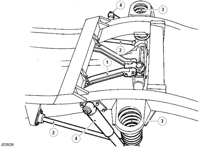
| Pos. | Spare No | Name |
| 1 | parts | A-frame, upper control arm assembly |
| 2 | - | Lower arm |
| 3 | - | Coil springs |
| 4 | - | Shock absorbers |
The rear suspension design features a rear axle with two steel lower control arms of round cross-section and a forged A-frame with an upper control arm assembly. This system provides maximum axle mobility and wheel travel while maintaining lateral and directional stability.
The lever is secured with a single nut to a support on the chassis, which contains a bracket with a rubber bushing, which is supported by three fastening elements. A rubber bushing with a compression ring and a single fastening bolt is used to secure the lever to its support on the bridge.
The upper control arm assembly is located on the rear differential housing and is secured by a ball joint. Two brackets, bolted to the chassis crossmember, support either side of the control arm assembly A-frame, which is secured by single bolts.
The 110/130 models can be fitted with an optional Boge Hydromat self-levelling unit, providing additional support when the vehicle is used to carry heavier loads.
Two rubber bushings with retaining clips secure the rear of the anti-roll bar (if available) relative to the chassis supports, while the struts with bushings connect the front part of the stabilizer to the axle.
Conventional long-travel coil springs and hydraulic shock absorbers are used to control body movements. The shock absorbers are attached to support brackets on the chassis, and the lower welded supports are welded to the rear axle. Locking plates are used to attach the coil springs to the supports on the axle, and welded brackets welded to the chassis are used to attach the springs to the upper mountings.
Comments on this article