Special tool(s)
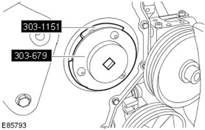
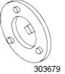 | Crankshaft Oil Seal Remover/Installer 303-679 |
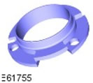 | Fuel Pump Sprocket Locking Tool 303-1151 |
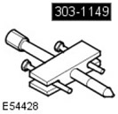 | Crankshaft Damping Clutch Pulley Remover 303-1149 |
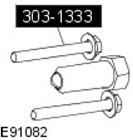 | Fuel Pump Puller 303-1333 |
Removal
Warnings:
- Some fuel will inevitably spill during this operation. Make sure that all necessary precautions are taken to prevent fire and explosion.
- Do not carry or use a cell phone while working with or in the immediate vicinity of any fuel related components. There is a risk of ignition of flammable vapors. Failure to follow these instructions may result in injury.
- Do not smoke or carry a lighted cigarette or open flame of any type when working on or near fuel-related components. There is a risk of ignition of flammable vapors. Failure to follow these instructions may result in injury.
- If fuel gets into your eyes, rinse them with cold water or a special eye wash solution and seek medical attention immediately.
- Wash your hands thoroughly after handling fuel, as prolonged contact with the skin may cause irritation. If irritation occurs, seek medical attention.
- Do not perform any repairs to the fuel system while the engine is running. Fuel pressure in the system can reach 2000 bar. Failure to follow this instruction may result in injury.
CAUTION: Diesel fuel injection equipment is manufactured to very precise tolerances and very small clearances. Therefore, absolute cleanliness is required when working on these components. Be sure to insert new plugs into all open ports and lines. Failure to do so may result in dirt entering the fuel injection system.
1. Disconnect the ground wire from the battery.
For more information, refer to the chapter: Disconnecting and connecting the battery (414-01 Battery, Battery Mounting and Cables, General Procedures).
2. Remove the accessory drive element bracket.
For more information, refer to the chapter: Belt/Accessory Chain Tensioner Bracket (303-05 Accessory Drive - ID4 2.4L Diesel Engine, Removal and Installation).
3. Remove the brake system vacuum pump.
For more information, refer to the chapter: Brake Vacuum Pump (206-07 Brake booster, Removal and installation).
4.
WARNING: Never work on a vehicle supported only by a jack. Always support the vehicle with special stands.
Raise and support the vehicle.
For more information, refer to the chapter: Lifting the vehicle (100-02 Jacking and lifting a car on a lift, Description and operating principle).
5. Drain the fluid from the cooling system.
For more information, refer to the chapter: Draining/filling coolant and bleeding air from the cooling system (303-03 Engine Cooling - ID4 2.4L Diesel Engine, General Procedures).
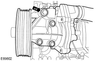
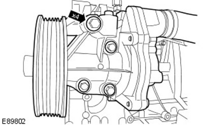
6. Remove the water pump.
- Remove 4 bolts.
- Remove the gasket and dispose of it.
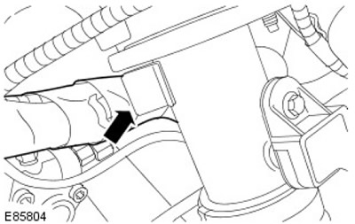
7. Disconnect the wiring harness.
8. Using a vacuum cleaner, remove foreign material from the high-pressure fuel supply lines, fuel rails and high-pressure fuel pump.
For more information, refer to the chapter: Cleaning the fuel injection system components (303-04A Fuel Delivery and Controls - ID4 2.4L Diesel Engine, General Procedures).
9.
CAUTION: Plug all openings. Use new caps.
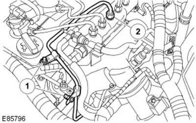
Release the fuel pump pressure line
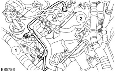
- 1. Remove two bolts.
- 2. Remove the fuel pump pressure line fitting
10.
CAUTION: Plug all openings. Use new caps.
Disconnect the fuel injector from the high pressure fuel pump fuel line.
11.
CAUTION: Plug all openings. Use new caps.
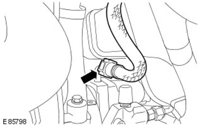
Disconnect the fuel return line.
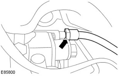
12. Disconnect the fuel metering valve and fuel temperature sensor.
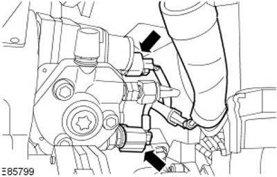
13.
CAUTION: Plug all openings. Use new caps.
Remove and discard the high pressure fuel pump fuel supply line.
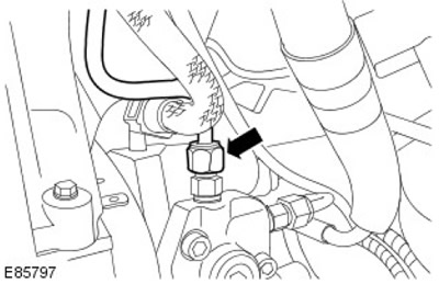
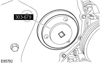
14. Using the special tool, remove the high pressure fuel pump drive gear cover.
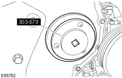
15. Install special tools.
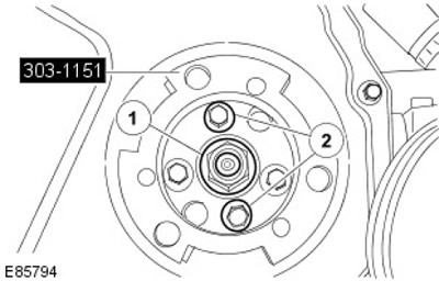
16. Remove the high pressure fuel pump drive gear.
- 1. Remove the nut.
- 2. Remove two bolts.
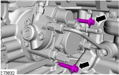
17. Remove 2 bolts from the high pressure fuel pump.
18. Using the special tool, remove the high pressure fuel pump.
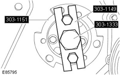
19. Remove the high pressure fuel pump. Remove the sealing ring and dispose of it.
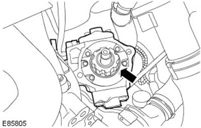
Installation
1. Install the high pressure fuel pump.
- Clean the contact surfaces of the parts.
- Install the sealing ring.
- Install the high pressure fuel pump bolts.
2. Secure the high pressure fuel pump. Tighten the bolts (tightening torque 23 Nm).
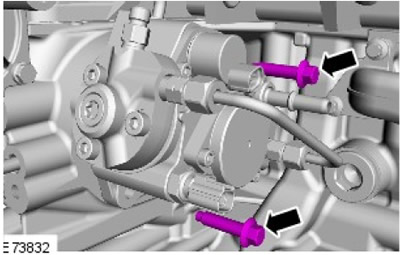
3. Secure the high pressure fuel pump drive gear.
- 1. Tighten the nut (tightening torque 64 Nm).
- 2. Tighten the bolts to 33 Nm.
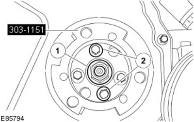
4. Remove the special tool.
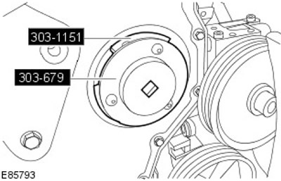
5. Using the special tool, install the high pressure fuel pump drive gear cover.
6.
NOTE: Remove and discard plugs.
Install the new high-pressure fuel supply line without tightening the bolts. Install the high-pressure line clamps without tightening.
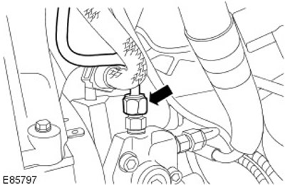
7. Install the high pressure fuel pump pressure fuel line. Tighten (tightening torque 35 Nm).
8. Secure the high pressure fuel pump pressure line.
- 1. Tighten (tightening torque 10 Nm).
- 2. Tighten (tightening torque 35 Nm).
9. Connect the fuel metering valve and fuel temperature sensor.
10.
NOTE: Remove and discard plugs.
Connect the fuel return line.
11. Secure the wiring harness to the intake manifold.
12. Install the water pump.
- Install a new gasket.
- Tighten it up (tightening torque 23 Nm).
13. Fill the cooling system with coolant and bleed air from the system.
For more information, refer to the chapter: Draining/filling coolant and bleeding air from the cooling system (303-03 Engine Cooling - ID4 2.4L Diesel Engine, General Procedures).
14. Install the brake system vacuum pump.
For more information, refer to the chapter: Brake Vacuum Pump (206-07 Brake booster, Removal and installation).
15. Install the accessory drive component bracket.
For more information, refer to the chapter: Belt Tensioner/Accessory Drive Bracket (303-05 Accessory Drive - ID4 2.4L Diesel Engine, Removal and Installation).
16. Connect the ground wire to the battery.
For more information, refer to the chapter: Connecting the Battery (414-01 Battery, Battery Mounting and Cables, General Procedures).
17. Using the Land Rover recommended diagnostic system, perform the fuel pump learn procedure.
Comments on this article