General Equipment
Pneumatic vacuum gun.
Removing
Warnings:
- Some fuel will inevitably spill during this operation. Ensure that all necessary precautions have been taken to prevent fire and explosion.
- Do not carry or use a cell phone while working on or in the vicinity of any fuel related items. There is a danger of ignition of flammable vapours. Failure to follow these instructions may result in injury.
- Do not smoke or walk with a lit cigarette or any type of open flame while working on or near fuel related items. There is a danger of ignition of flammable vapours. Failure to follow these instructions may result in injury.
- If fuel gets in your eyes, rinse them with cold water or special eyewash solution and seek immediate medical attention.
- Wash your hands thoroughly after handling fuel as prolonged skin contact with fuel may cause irritation. Seek medical attention if irritation occurs.
- Do not carry out any repairs to the fuel system while the engine is running. The fuel pressure in the system can reach 2000 bar. Failure to follow this instruction may result in injury.
Caveats:
- Diesel fuel injection equipment is manufactured to very precise tolerances and very close clearances. Therefore, when working with these nodes, absolute cleanliness is required.
- Be sure to install new plugs in all open holes and piping. Failure to follow this instruction may lead to the penetration of dirt into the fuel injection system.
- Be sure to perform the cleaning procedure before carrying out any repairs to the fuel injection system components. Failure to follow this instruction may lead to the penetration of dirt into the fuel injection system.
- Do not disconnect the fuel injector electrical connectors while the engine is running. Failure to do so may result in serious engine damage.
- Keep the workshop area where the vehicle is being worked on as clean and dust-free as possible. Dirt and dust from working on the clutch, brakes, or from machining or welding can contaminate the fuel system and lead to malfunctions later.
1. Disconnect the wire "masses" from the battery.
For more information, see the chapter: Disconnecting and connecting the battery (414-01 Battery, Battery Mount and Wires, General Procedures).
2. Remove the engine cover.
For more information, see chapter: Engine cover (501-05 Interior trim, Removal and installation).
3. Using a vacuum cleaner, remove foreign matter from the high pressure fuel supply lines, fuel manifolds and high pressure fuel pump.
For more information, refer to the chapter: Cleaning the fuel injection system components (303-04A Fuel Supply and Controls - ID4 2.4L Diesel Engine, General Procedures).
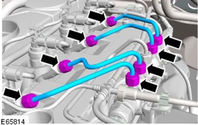
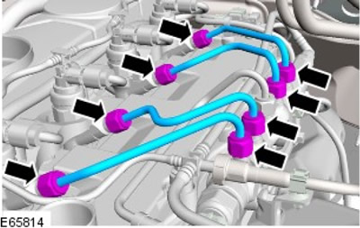
4.
Caveats:
- Do not strike the sealing lens of the high pressure fuel supply line, as this may damage the ends of the line and allow dirt to enter the fuel injection system.
- Plug all openings. Use new caps.
Remove the 4 high pressure fuel feed lines and discard them.
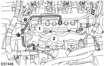
5.
Caveats:
- Do not strike the sealing lens of the high pressure fuel supply line, as this may damage the ends of the line and allow dirt to enter the fuel injection system.
- Plug all openings. Use new caps.
Remove the high pressure fuel supply line and discard it.
- 1. Release the clips.
- 2. Remove the fuel rail from the fuel manifold.
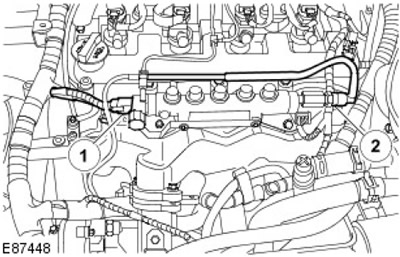
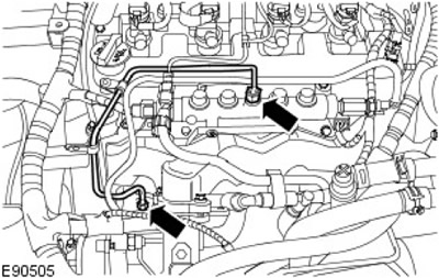
6.
CAUTION: Plug all openings. Use new caps.
Disconnect the fuel rail pressure sensor electrical connector (FRP) and fuel return line.
- 1. Disconnect the FRP sensor electrical connector.
- 2. Disconnect the fuel manifold return line.
7. Remove the intake manifold.
For more information, refer to the chapter: Intake Manifold (303-01 Engine - Diesel engine ID4 2.4L, Car repair).
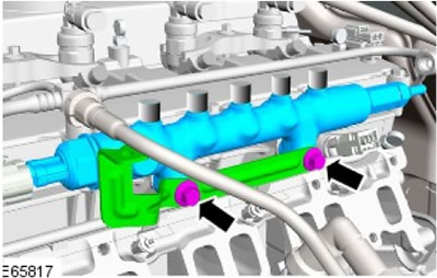
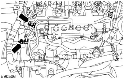
8. Remove the fuel rail.
- Turn out two bolts.
- Remove the bracket.
Installation
Warnings:
- Some fuel will inevitably spill during this operation. Ensure that all necessary precautions have been taken to prevent fire and explosion.
- Do not carry or use a cell phone while working on or in the vicinity of any fuel related items. There is a danger of ignition of flammable vapours. Failure to follow these instructions may result in injury.
- Do not smoke or walk with a lit cigarette or any type of open flame while working on or near fuel related items. There is a danger of ignition of flammable vapours. Failure to follow these instructions may result in injury.
- If fuel gets in your eyes, rinse them with cold water or special eyewash solution and seek immediate medical attention.
- Wash your hands thoroughly after handling fuel as prolonged skin contact with fuel may cause irritation. Seek medical attention if irritation occurs.
- Do not carry out any repairs to the fuel system while the engine is running. The fuel pressure in the system can reach 2000 bar. Failure to follow this instruction may result in injury.
Caveats:
- Diesel fuel injection equipment is manufactured to very precise tolerances and very close clearances. Therefore, when working with these nodes, absolute cleanliness is required.
- Be sure to install new plugs in all open holes and piping. Failure to follow this instruction may lead to the penetration of dirt into the fuel injection system.
- Be sure to perform the cleaning procedure before carrying out any repairs to the fuel injection system components. Failure to follow this instruction may lead to the penetration of dirt into the fuel injection system.
- Do not disconnect the fuel injector electrical connectors while the engine is running. Failure to do so may result in serious engine damage.
- Keep the workshop area where the vehicle is being worked on as clean and dust-free as possible. Dirt and dust from working on the clutch, brakes, or from machining or welding can contaminate the fuel system and lead to malfunctions later.
1.
CAUTION: At this stage, hand-tighten the bolts only.
NOTE: Clean the contact surfaces of the parts.
Install the fuel manifold.
- Install the bracket.
- Screw in the bolts, but do not tighten them.
2.
Caveats:
- Apply pressure to the high pressure fuel supply line to keep the sealing lenses in contact with the cones of the fuel injectors and fuel rail when connected.
- Do not strike the sealing lenses of the high pressure fuel supply line, as this may damage the ends of the line and allow dirt to enter the fuel injection system.
- At this stage, tighten the connections by hand only.
NOTE: Remove and discard plugs.
Install a new high pressure fuel supply line, but do not permanently fix it.
3.
Caveats:
- Apply pressure to the high pressure fuel supply line to keep the sealing lenses in contact with the cones of the fuel injectors and fuel rail when connected.
- Do not strike the sealing lenses of the high pressure fuel supply line, as this may damage the ends of the line and allow dirt to enter the fuel injection system.
- At this stage, tighten the connections by hand only.
NOTE: Remove and discard plugs.
Install new high pressure fuel feed lines, but do not permanently fasten them.
4. Attach the fuel manifold.
- Stage 1: Tighten the bolts to 8 Nm.
- Stage 2: Tighten the bolts (tightening torque 23 Nm).

5. Attach the high pressure fuel lines.
- Stage 1: Tighten the connection (tightening torque 5 Nm).
- Stage 2: Tighten the connection (tightening torque 35 Nm).
6. Attach the fuel supply line to the fuel manifold.
- Stage 1: Tighten the connection (tightening torque 5 Nm).
- Stage 2: Tighten the connection (tightening torque 35 Nm).
7. Tighten (tightening torque 10 Nm).
8. Reinstall the intake manifold.
For more information, refer to the chapter: Intake Manifold (303-01 Engine - Diesel engine ID4 2.4L, Car repair).
9. Connect the FRP sensor electrical connector.
10.
NOTE: Remove and discard plugs.
Connect the fuel return line.
11. Replace the engine cover.
For more information, see chapter: Engine cover (501-05 Interior trim, Removal and installation).
12. Connect the wire "masses" to the battery.
For more information, see the chapter: Connecting the Battery (414-01 Battery, Battery Mount and Wires, General Procedures).
13. Check the fuel system for leaks using the Land Rover approved diagnostic system.
Comments on this article