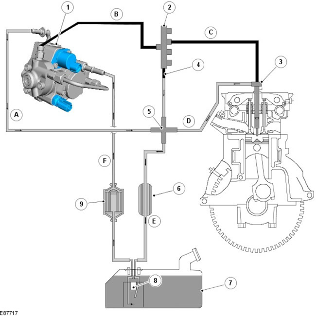
Location of elements
| Pos. | spare part no | Name |
| A | - | Fuel return from high pressure pump |
| B | - | High pressure fuel line |
| C | - | High pressure fuel line |
| D | - | Drain fuel line |
| E | - | Pipeline for removing fuel to the fuel tank |
| F | - | Fuel supply |
| 1 | - | High pressure pump |
| 2 | - | fuel manifold |
| 3 | - | Fuel burner |
| 4 | - | Pressure limiting valve |
| 5 | - | Tee |
| 6 | - | Fuel System Radiator |
| 7 | - | Fuel tank |
| 8 | - | Fill level sensor |
| 9 | - | Fuel filter |
Fuel is drawn from the fuel tank through the fuel filter by means of a transfer pump built into the high pressure pump. The high pressure pump compresses the fuel and delivers it to the fuel manifold. Depending on the requirements for fuel injection, the required pressure is created by the injectors. Fuel escaping from the injectors and/or returning from the high pressure pump is returned to the fuel tank.
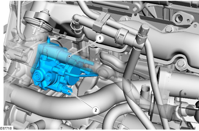
High pressure fuel pump (injection pump)
| Pos. | spare part no | Name |
| 1 | - | Pump capacity regulator (VCV) |
| 2 | - | Fuel temperature sensor |
The high pressure fuel pump is the interface between the low and high pressure systems. Its purpose is to supply fuel at the required pressure under all operating conditions throughout the life of the vehicle.
The fuel pump is located under the intake manifold and is driven by a timing chain on the front of the engine. The pump assembly includes a low pressure pump, a high pressure pump, VCV and a fuel temperature sensor.
The high pressure pump receives fuel at transfer pressure from the transfer pump and increases the fuel pressure. The high pressure fuel is then transferred from the high pressure pump to the fuel manifold.
| Pos. | spare part no | Name |
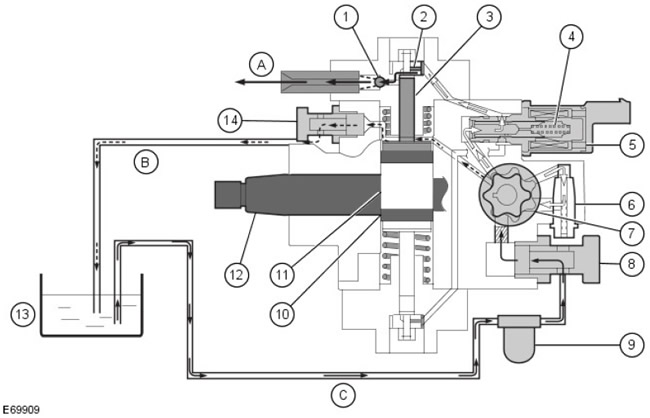
| A | - | High pressure fuel to fuel rail |
| B | - | Fuel return line |
| C | - | Fuel supply |
| 1 | - | High pressure chamber outlet valve |
| 2 | - | High pressure chamber inlet valve |
| 3 | - | pump plunger |
| 4 | - | VCV return spring |
| 5 | - | Pump capacity regulator (VCV) |
| 6 | - | Inlet pressure control valve (pump internal pressure) |
| 7 | - | Low pressure pump |
| 8 | - | fuel inlet |
| 9 | - | Fuel filter |
| 10 | - | Eccentric ring |
| 11 | - | eccentric cam |
| 12 | - | half shaft |
| 13 | - | Fuel tank |
| 14 | - | Fuel bypass valve |
The transfer pump receives fuel from the fuel tank through the intake port (8). The internal pressure of the pump is controlled by the inlet pressure control valve (6), providing the necessary lubrication and cooling of the high pressure pump components. Excess fuel is transferred to the inlet side of the low pressure pump (7) through the intake pressure control valve, while part of the fuel enters the VCV (5) from the low pressure pump. The amount of fuel supplied to the pressure chambers is given by the cross section of the VCV valve bore. Small restricted hole in bypass valve (14) ensures automatic venting of the high pressure pump. The entire low pressure system is designed to allow a certain amount of fuel to flow back into the fuel tank through the pressure bypass control line to help cool the high pressure pump.
Two high pressure chambers are used to generate high pressure (1 and 2), one for each pump plunger (3). The pump plungers are driven by an eccentric cam (11), which in turn is driven by a drive shaft (12). The high pressure pump constantly generates high system pressure for the fuel rail.
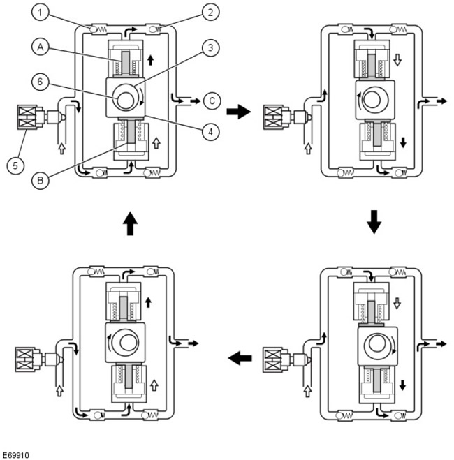
Principle of high pressure generation
| Pos. | spare part no | Name |
| A | - | Pump plunger 1 |
| B | - | Pump plunger 2 |
| C | - | To fuel manifold |
| 1 | - | Inlet valve |
| 2 | - | Exhaust valve |
| 3 | - | eccentric cam |
| 4 | - | Eccentric ring |
| 5 | - | Fuel metering valve |
| 6 | - | half shaft |
Rotary movement of the drive shaft (6) converted into reciprocating motion of an eccentric cam (3). Eccentric ring (4) transmits reciprocating motion to the pump plungers (1 and 2).
The pump plungers are offset by 180 degrees. This means that during the reciprocating motion, the pump plunger 1 moves in the opposite direction relative to the pump plunger 2.
When the eccentric pushes plunger 1 up, the latter moves to TDC, compressing the fuel and pushing it into the fuel manifold through the exhaust valve (2). Inlet valve (1) pressed into its seat by feed pressure. The pump plunger 2 moves under the influence of the extension spring in the direction of bottom dead center (NMT). Due to the high pressure in the fuel manifold, the exhaust valve is pressed into its seat. The pump's internal pressure opens the intake valve and fuel flows into the high pressure chamber.
When the eccentric pushes the plunger down, the process occurs in the opposite direction.
The VCV valve is located on the high pressure fuel pump. The valve regulates the fuel supply (and hence the amount of fuel) from the transfer pump to the high pressure pump plungers, depending on the fuel pressure in the manifold. This makes it possible to match the supply of the high pressure fuel pump to the demands of the engine on the low pressure side. At the same time, the amount of fuel going to the return drain is reduced to a minimum. In addition, this adjustment reduces the energy consumption of the high pressure fuel pump, improving engine efficiency.
For more information, see the chapter: Electronic controls (303-14 Electronic Controls - Diesel Engine ID4 2.4L, Description and Operation).
After replacing the high pressure pump and/or ECM, the VCV must be calibrated using Land Rover approved diagnostic equipment.
The fuel temperature sensor is also located on the injection pump. The ECM constantly monitors fuel temperature to properly respond to changes in fuel density based on fuel temperature.
For more information, see the chapter: Electronic controls (303-14 Electronic Controls - Diesel Engine ID4 2.4L, Description and Operation).
If the fuel temperature sensor is disconnected, the engine will run under power and a DTC will be generated.
Fuel manifold
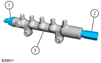
| Pos. | spare part no | Name |
| 1 | - | Fuel pressure sensor |
| 2 | - | Pressure limiting valve |
| 3 | - | fuel manifold |
The fuel manifold performs the following functions:
- accumulates fuel under high pressure
- minimizes pressure fluctuations
Pressure fluctuations occur in the high pressure fuel system due to operating movements in the high pressure chambers of the fuel pump and the opening and closing of solenoid valves in the fuel injectors. Therefore, the fuel manifold is designed to provide sufficient volume to minimize pressure fluctuations, while also providing fuel pressure build-up for quick starts in the shortest possible time.
The fuel supplied by the high pressure pump passes through the high pressure line to the high pressure accumulator. The fuel is then sent through four injector fuel lines, which are of the same length, to the individual fuel injectors. When fuel is taken from the fuel rail for the injection process, the pressure in the fuel rail is kept nearly constant.
The pressure relief valve opens at a fuel pressure of approximately 2000 bar. It serves as a safety device in case of malfunctions in the high pressure system. The valve is replaceable: after a single actuation, it must be replaced, since its further tightness is not guaranteed. Pressure relief valve actuation is detected by the ECM and an appropriate DTC is generated (DTC) and the warning lamp for malfunctioning emission control systems is activated (MIL).
The fuel rail pressure sensor is located at its far end. The sensor measures the fuel pressure in the fuel rail. The sensor signal is used by the ECM to control the amount of fuel delivered to the fuel rail.
For more information, see the chapter: Electronic controls (303-14 Electronic Controls - Diesel Engine ID4 2.4L, Description and Operation).
If the pressure sensor is disconnected, the engine enters a low power mode and a DTC is generated. The sensor is not serviced and is supplied as part of a new manifold with pressure relief valve.
Fuel injectors
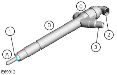
| Pos. | spare part no | Name |
| A | - | Nozzle |
| B | - | Hydraulic Servo System |
| C | - | Solenoid valve |
| 1 | - | Combustion chamber seal |
| 2 | - | Electrical connection - solenoid valve |
| 3 | - | high pressure fuel line fitting |
The 4 fuel injectors are located in the cylinder head, between the 4 valves of each cylinder. Each injector is sealed in the cylinder head with a copper washer. Each injector has an electrical connector for power supply, as well as connectors for connection to the ECM. Fuel injectors are controlled directly by the ECM for fuel metering (start of injection and amount of injected fuel). A fuel return pipe is mounted on top of each injector, through which fuel passing through the injector can be returned to the fuel tank.
NOTE: The copper washers sealing the injectors in the cylinder head must not be reused.
Each nozzle is equipped with a solenoid valve; when power is applied to the solenoid, the valve ball rises above the seat. This allows the compressed fuel to lift the injector needle valve and inject fuel into the cylinder as a fine mist. Fuel penetrating past the ball valve is directed to the return line, which is connected to the return line of the injection pump.
The ECM controls the solenoid valve for each injector individually, providing a ground to open the injector orifice at the right moment and for a precisely defined period of time, producing precisely metered fuel injection into the cylinder. The ECM uses signals from other sensors and a fuel delivery program to ensure that the correct amount of fuel is delivered at the right time to maximize fuel efficiency and minimize emissions.
Fuel injector solenoid valve
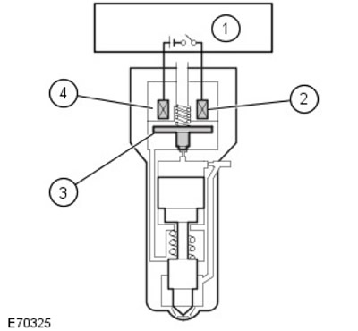
| Pos. | spare part no | Name |
| 1 | - | ECM |
| 2 | - | Winding |
| 3 | - | Electromagnet armature |
| 4 | - | Solenoid valve |
The ECM energizes the injector solenoid valves in 3 stages:
- 1. 18 A
- 2. 8 A
- 3.4 A
To start the injection process, an increased initial starting current is supplied to the solenoid valve so that it opens faster. After a short period of time, the starting current is reduced to a low holding current.
For optimum fuel economy, the ECM must receive injector change data by entering a 16-digit identification number. Inside the hydraulic servo system, there are various chokes with extremely small diameters to meet process tolerances. These manufacturing tolerances are specified as part of the identification number, which is located on the fuel injector body.

| Pos. | spare part no | Name |
| 1 | - | Solenoid valve |
| 2 | - | 16 digit identification number |
| 3 | - | Bypass connection |
NOTE: If identification numbers are not entered properly using Land Rover approved diagnostic equipment, the following problems may occur:
- Increased black smoke
- Poor idle performance
- Increased combustion noise
In addition, the fuel injectors must be configured after downloading new ECM software using Land Rover approved diagnostic equipment.
The ECM detects injector malfunctions based on the power consumption of the solenoid valves. If the fuel injector is malfunctioning, any of the following symptoms may be present:
- Misfires
- Idle problems
- Deterioration of the energy performance of the engine
- Increase in fuel consumption
- Difficult cold start
- Difficulty starting a hot engine
- Increased opacity of exhaust gases
Comments on this article