


Contents: Removal ⇩ Installation ⇩
Removal
NOTE: The steps described in this procedure may be included in the installation procedure.
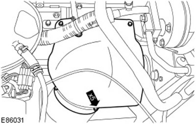
1. Remove the turbocharger heat shield.
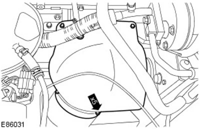
2.
Warnings:
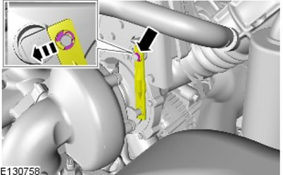
- Do not apply force that may deform the variable geometry turbocharger drive shaft components.
- When removing the variable geometry turbocharger drive shaft, do not apply rotational force as this may damage the worm gear.
Disconnect the connecting rod from the drive. It may be necessary to insert a suitable tool between the shoulder of the shaft and the drive rod and rock it from side to side.
3.
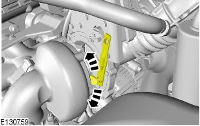
NOTE: Movement may be difficult at first due to carbon build-up.
Using your finger, move the variable geometry turbocharger actuator to ensure that there is sufficient travel. Move it 10-20 times to ensure sufficient travel.
4.
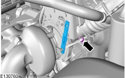
CAUTION: Do not apply excessive force or leverage to the crank arm as this may deform the crank arm or damage the turbine mechanism.
Remove the turbocharger actuator connecting rod. Use a penetrating spray if necessary.
5.
NOTE: Very fine wet and dry paper may be required for polishing and corrosion removal.
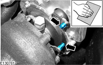
Clean the surfaces of the drive studs and turbocharger.
- Apply a penetrating lubricant to the turbocharger and drive studs.
- Clean the surfaces of the studs.
Installation
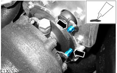
1. Apply recommended high temperature grease (land Rover part number LR029042) on both studs, paying special attention to ensure that they are completely covered.
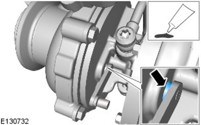
2. Apply recommended high temperature grease (land Rover part number LR029042) on the inner surface of the contact of the bushing with the turbocharger.
3. Install the new turbocharger actuator rod.
- Install new mounting clamps.
- Using a suitable tool, rotate the new fasteners in the slots to ensure proper installation.
- Apply protective grease to the drive studs and drive rod joints.
4. Tighten the bolts to 10 Nm (7 lbs/ft).
Comments on this article