Contents: Removal ⇩ Installation ⇩
Removal
All cars
CAUTION: Do not work on a vehicle supported only by a jack. Be sure to support the vehicle securely.
Raise and support the vehicle.
2. Open the hood.
Left-hand drive vehicles
3.
CAUTION: Do not turn the steering wheel if the lower steering column shaft is disconnected, as this may damage the coil spring and the switches located on the steering wheel.
CAUTION: Make sure the steering system is pointing straight ahead.
NOTE: Mark the installation position.
Loosen the bolt securing the lower steering column shaft to the upper steering column shaft.
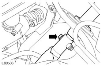
All cars
4. Remove the left front wheel.
5. Remove the gearbox guard. Unscrew 6 bolts.
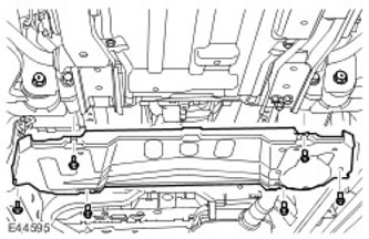
6. Remove the engine protection. For more information, refer to Engine Protection (76.10.50)
Left-hand drive vehicles
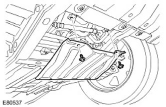
7. Remove the radiator panel. Unscrew 2 bolts.
All cars
8. Release the lower catalytic converter support insulator.
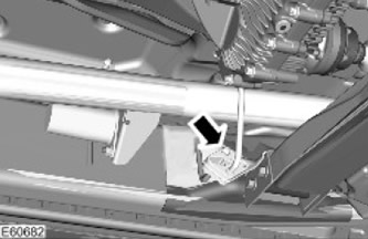
9. Remove the transmission support insulator bolt. Support the transmission using a transmission jack.
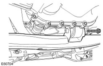
10. With the help of another mechanic, remove the transmission support crossmember. Remove the 4 nuts and bolts.
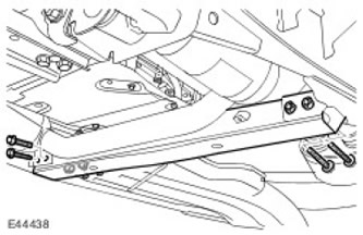
11. With the help of another mechanic, remove the lower catalytic converter.
- Release the clamp.
- Unscrew the three nuts and tighten them.
- Remove the gasket and discard it.
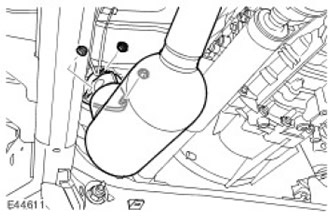
12. Remove the front exhaust system heat shield.
- Unscrew the three nuts.
- Remove the bolt.
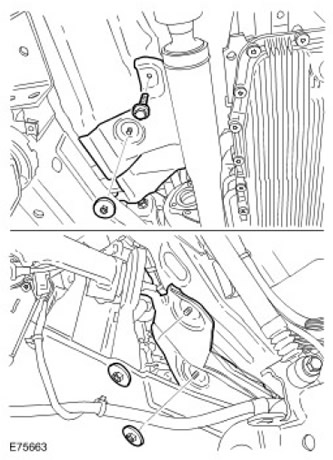
13. Install the gearbox support crossmember.
- Install, but do not fully tighten at this stage, the 2 transmission crossmember bolts.
- Install, but do not fully tighten, the transmission support insulator bolt at this stage.
- Remove the jack.
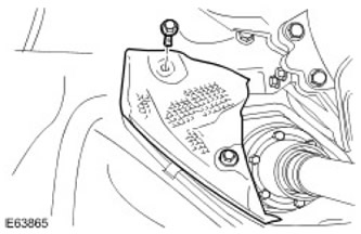
15. Remove the turbocharger support bracket.
- Remove 2 bolts.
- Unscrew the nut.
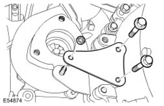
16. Remove 2 bolts from turbocharger support bracket.
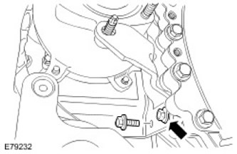
17. Lower the turbocharger lower nut.
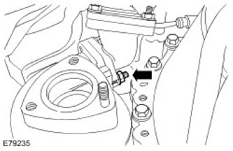
18. Remove the upper left control arm. For more information, refer to Upper Control Arm (60.35.01)
19. Turn the ignition key to position I. Turn the steering wheel so that the head of the lower steering column shaft bolt is visible through the left wheel arch.
20.
CAUTION: Do not turn the steering wheel if the lower steering column shaft is disconnected, as this may damage the coil spring and the switches located on the steering wheel.
Remove and discard the lower steering column shaft bolt.
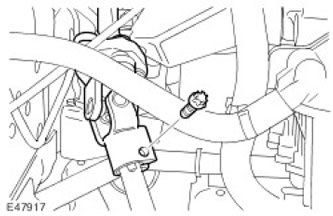
21. Turn the steering wheel to the straight-ahead position. Remove the ignition key.
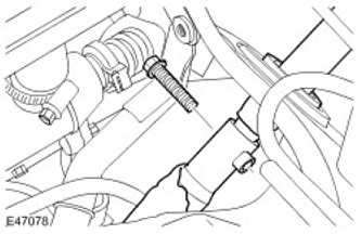
22. Remove the lower steering column shaft. Unscrew and discard the upper bolt of the lower steering column shaft.
The original was published on the portal (LRman.ru)
All cars
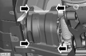
23. Remove the lower fender splash guard trim. Remove the 4 clips.
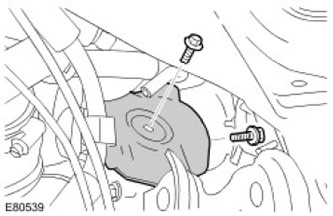
24. Remove the turbocharger heat shield. Remove 2 bolts.
25.
CAUTION: To avoid contamination of the system, be sure to plug all open connections.
Disconnect the turbocharger oil supply line.
- Remove the turbocharger banjo bolt.
- Remove and discard the sealing washers.
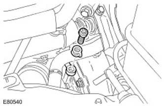
26.
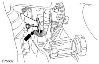
CAUTION: To avoid contamination of the system, be sure to plug all open connections.
Remove the turbocharger oil return line bolt. Disconnect the wiring harness clamp.
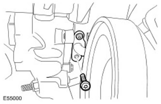
27. Remove the turbocharger return oil line.
- Remove 2 bolts.
- Remove the gasket and discard it.
- Remove the sealing ring and discard it.
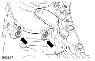
28. Remove the turbocharger support bracket. Remove 2 bolts.
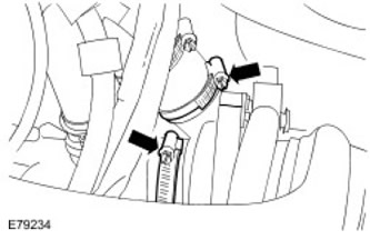
29. Release the turbocharger outlet and exhaust pipe clamps.
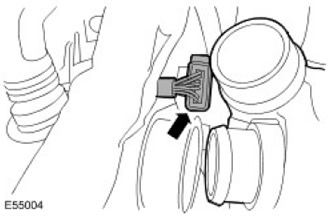
30. Disconnect the turbocharger electrical connector.
31.
CAUTION: Always wear safety glasses.
CAUTION: Drill out turbocharger studs only.
CAUTION: Make sure that the drill depth does not exceed 14 mm.
Carefully drill out the 2 top turbocharger studs.
- Punch the 2 upper turbocharger studs.
- Drill a pilot hole in the center of the turbocharger studs; gradually drill out the studs until you have an 8mm hole.

32. With the help of another mechanic, remove the turbocharger. Lower the lower turbocharger nut.
Installation
All cars
1.
CAUTION: Always wear safety glasses.
CAUTION: Do not direct the high pressure nozzle jet at the skin as high pressure air may penetrate subcutaneous tissue and cause serious injury.
CAUTION: Maintain high pressure equipment in good condition and check and service it regularly, paying particular attention to joints and fittings.
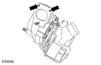
Drill two 8mm diameter holes in the turbocharger as shown in the picture. Clean the turbocharger and blow it out with compressed air.
2. Install the new turbocharger lower bore stud.
3. With the help of another mechanic, install the turbocharger.
- Clean the turbocharger mating surfaces.
- Check the position of the turbocharger inlet and outlet pipes.
5. Tighten the turbocharger lower nut to 24 Nm.
6. Connect the turbocharger electrical connector.
7. Tighten the turbocharger inlet and outlet pipe clamps.
8. Install the turbocharger support bracket. Tighten the bolts to 23 Nm.
9. Connect the turbocharger oil supply line.
- Install new sealing washers.
- Tighten the turbocharger oil supply line bolt to 30 Nm.
11. Install the 2 turbocharger oil return line bolts.
- Install a new gasket.
- Install a new O-ring.
- Tighten the 2 bolts to 10 Nm.
13. Install the lower fender splash guard trim. Install the 4 clips.
Left-hand drive vehicles
14. Install the lower steering column shaft.
- Connect the lower steering column shaft to the upper steering column shaft.
- Attach the universal joint to the steering gear.
15. Install, but do not fully tighten at this stage, the new lower steering column shaft to upper steering column shaft bolt.
16.
CAUTION: Do not turn the steering wheel if the lower steering column shaft is disconnected, as this may damage the coil spring and the switches located on the steering wheel.
Turn the ignition key to position I. Turn the steering wheel so that the hole in the lower steering column shaft bolt is visible through the left wheel arch.
17. Screw in the bolt securing the lower steering column shaft to the steering gear. Install a new bolt and tighten to 30 Nm.
18. Turn the steering wheel to the straight-ahead position. Remove the ignition key.
19. Tighten the lower steering column shaft to upper steering column shaft mounting bolt to 30 Nm.
All cars
20. Install the left upper control arm. For more information, refer to Upper Control Arm (60.35.01)
21. Install the 2 turbocharger support bracket bolts. Tighten the 2 bolts to 23 Nm.
22. Install the turbocharger support bracket.
- Install the turbocharger support bracket stud.
- Tighten the 2 bolts to 48 Nm.
- Tighten the nut to 25 Nm.
24. Remove the transmission support crossmember. Using a transmission jack, support the transmission.
25. Install the front exhaust heat shield.
- Screw on three nuts.
- Screw in the bolt.
- Install new studs and nuts.
- Install a new gasket.
- Tighten the lower catalytic converter nuts and clamp to 48 Nm.
- Tighten the nuts and bolts to 90 Nm.
- Install the gearbox support insulator bolt and tighten to 175 Nm.
- Remove the jack.
Left-hand drive vehicles
29. Install the radiator panel. Tighten the 2 bolts to 10 Nm.
All cars
30. Install the engine protection. For more information, refer to Engine Protection (76.10.50)
31. Install the gearbox guard. Tighten the bolts to 10 Nm.
32. Install the left front wheel. Tighten the wheel nuts to 140 Nm.
33. Check the engine oil level and top up if necessary.
34. Close the hood.
Comments on this article