Contents: Component arrangement ⇩ General information ⇩ Intake manifold ⇩ Fuel pump ⇩ Throttle body ⇩ Inlet manifold ⇩ Fuel rail ⇩ Fuel pressure accumulator ⇩ Fuel temperature sensor ⇩ Nozzles ⇩
Component arrangement
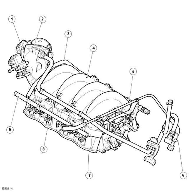
| Item name | Spare part catalog number | Description |
| 1 | - | Electronic throttle body |
| 2 | - | Inlet manifold |
| 3 | - | Fuel rail connection tube |
| 4 | - | Intake manifold |
| 5 | - | Right fuel rail |
| 6 | - | Fuel supply pipe |
| 7 | - | Fuel injector housing |
| 8 | - | Nozzles (8 pcs.) |
| 9 | - | Left fuel rail |
General information
The main components of the fuel injection system are the intake manifold, fuel pump, fuel rails and eight injectors. The fuel pump delivers fuel under constant pressure from the tank to the fuel rail through a tube that runs along the transmission. The fuel rail distributes fuel evenly to all eight injectors. The fuel injectors, controlled by the ECM, are mounted in the fuel rails on each side of the intake manifold. The two fuel rails are connected to each other by a tube that runs along the front of the manifold. A Schrader valve is provided in the rail to check the fuel pressure during maintenance.
Intake manifold
The composite intake manifold is located at the top of the engine between the two cylinder banks. The manifold contains a central receiver from which eight intake manifolds run to each cylinder. The intake manifold is attached to the cylinder heads with 10 bolts.
Rubber gaskets installed in the intake manifold passages seal the joints between the passages and the cylinder heads. For more information, refer to Intake Air Distribution and Filtering (303-12B)
Fuel pump
The submersible electric fuel pump is mounted to the internal chassis of the tank at the bottom of the tangential port pickup cup. The fuel pressure regulator, which controls the fuel pressure in the fuel supply line that delivers fuel to the fuel rail, is located in a pipe located inside the fuel tank. For more information, refer to Fuel Tank and Lines (310-01B)
Throttle body
The electronic throttle body, located on the intake manifold, is designed to regulate engine torque. Its main components are the electronically controlled throttle valve, the accelerator pedal position (APP) sensor, and the engine control module (ECM).
The accelerator pedal position sensor is designed to determine the driver's requirements for engine power. (by adjusting the position of the throttle valve). The accelerator pedal position signal is sent to the engine control module (EMS) and is used to control the throttle position using an integrated electric actuator. Sensors mounted in the throttle body detect the position of the throttle valve and the rate of change of its position. For more information, refer to Electronic Engine Controls (303-14B)
Inlet manifold
The intake manifold connects the electronic throttle body and the intake manifold. The intake manifold has vacuum take-off points, which are used to control various systems. The lug at the rear of the manifold is designed to install the exhaust gas recirculation (EGR) valve.
Fuel rail
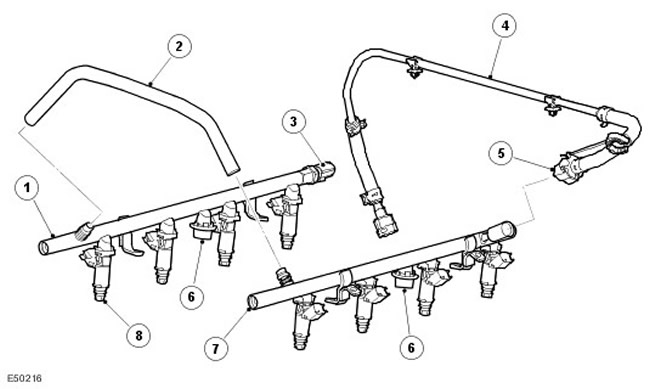
| Item name | Spare part catalog number | Description |
| 1 | - | Right fuel rail |
| 2 | - | Fuel rail connection tube |
| 3 | - | Fuel temperature sensor |
| 4 | - | Fuel supply pipe |
| 5 | - | Quick release fuel line connector |
| 6 | - | Fuel pressure accumulators |
| 7 | - | Left fuel rail |
| 8 | - | Nozzles (8 pcs.) |
Each fuel rail maintains a constant fuel pressure of 4.5 bar (0.45 MPa). Each fuel injector housing contains four injectors connected to the fuel rail. O-rings are used to seal the injectors in the fuel rail and in the intake manifold. A Cooper quick-release connector is used to connect the fuel supply pipe to the left fuel rail.
Each fuel rail has a fuel pressure accumulator attached to it, and a Schrader valve is installed at the front end of the left fuel rail. This allows the fuel pressure to be checked during servicing.
Fuel pressure accumulator
A fuel pressure accumulator is attached to the center of each fuel rail. The accumulators act as dampers, smoothing out the pulsations created by the pump and ensuring constant fuel pressure in the rails and injectors.
See the source on the website (lrman.ru)
Fuel temperature sensor
The fuel temperature sensor is mounted at the rear of the right fuel rail. The reverse temperature coefficient sensor is connected to the ECM by two wires. For more information, refer to Electronic Engine Controls (303-14B)
Nozzles
Eight fuel injectors with 12 nozzles and top fuel supply are installed on the fuel rails. Each injector is sealed with two O-rings, which should be replaced with new ones every time the injector is removed. To facilitate installation, the O-rings can be lubricated with a small amount of engine oil. The use of other types of lubricant is not allowed. The injectors supply fuel to the rear of the intake valves.
The ECM controls the operation of the injectors and solenoids. When power is removed from the injector solenoid coil, the needle closes the nozzle. Power is supplied to the injector coil through the main relay and the ground circuit is connected through the ECM. The injector is opened and closed by applying and removing ground to the ECM. When the injector is open, fuel is sprayed into the intake manifold and onto the rear of the intake valves. The ECM controls the amount of fuel delivered by the duration that the injector is open. For more information, refer to Electronic Engine Controls (303-14B)
Comments on this article