Contents: Component arrangement ⇩ General information ⇩ Intake manifold ⇩ Fuel pump ⇩ Throttle body ⇩ Fuel rail ⇩ Nozzles ⇩
Component arrangement
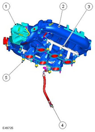
| Item name | Spare part catalog number | Description |
| 1 | - | Throttle body |
| 2 | - | Intake manifold |
| 3 | - | Fuel rail |
| 4 | - | Fuel supply pipe |
| 5 | - | Fuel injectors (6 pcs.) |
General information
The main components of the fuel injection system are the intake manifold, fuel pump, fuel rail and six injectors. The fuel pump delivers fuel under constant pressure from the tank to the fuel rail through a tube running under the body floor. The fuel rail distributes the fuel evenly to all six injectors.
Intake manifold
The intake manifold is located at the top of the engine. The manifold is made of composite material with metal inserts for fastening. The manifold consists of a central receiver from which individual intake pipes go to each cylinder. For more information, refer to Intake Air Distribution and Filtering (303-12A)
Fuel pump
The tank contains a submersible electric fuel pump and fuel pressure regulator. The pump module flange on the top of the tank allows access to the fuel pump for removal and installation.
During operation, the fuel pump maintains constant fuel pressure in the fuel rail. The pressure regulator controls the pressure. Excess fuel from the pressure regulator is supplied to the front transfer pump. Pressure regulation ensures that fuel is supplied to the fuel rail in a volume exceeding the maximum engine requirements.; therefore, constant fuel rail pressure is maintained regardless of operating conditions. For more information, refer to Fuel Tank and Lines (310-01A)
The fuel pump is controlled by the ECM via the fuel pump relay, which is located in the battery junction box (BJB).
When the ignition switch is turned to position II, the ECM provides ground to the fuel pump relay coil at terminal 95 of ECM connector C0634. The relay is energized momentarily to pressurize the fuel system. When the ECM detects from the engine speed (CKP) sensor that the engine is cranking, the ECM maintains the fuel pump relay energized as long as the engine is running. For additional information, refer to Electronic Engine Controls (303-14A)
Throttle body
The throttle body is located in front of and centered on the intake manifold. The electronic throttle controls engine torque. The electronic pedal assembly senses the throttle position. The pedal assembly sends a signal to the EMS, which opens the throttle to the desired angle using an electric motor built into the throttle body. Sensors mounted in the throttle body sense the position of the throttle and the rate at which it is changing. For more information, refer to Electronic Engine Controls (303-14A)
Fuel rail
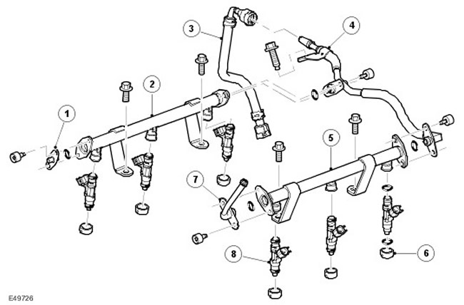
| Item name | Spare part catalog number | Description |
| 1 | - | End cap |
| 2 | - | Right fuel rail |
| 3 | - | Fuel supply pipe |
| 4 | - | Fuel supply line |
| 5 | - | Left fuel rail |
| 6 | - | Injector seat inserts |
| 7 | - | Schrader valve |
| 8 | - | Nozzles (6 pcs.) |
Each fuel rail maintains a constant fuel pressure of 4.5 bar. The rails are attached to the cylinder heads with two bolts. Three fuel injectors are installed in each cylinder head, connected by a fuel rail. O-rings are used to seal the injectors in the fuel rails and cylinder heads. A quick-release coupling connects the fuel supply line from the fuel tank to the fuel rail via a fuel supply pipe.
The fuel supply line is secured with a flange with two threaded holes on the rear of the left and right fuel rails. The fuel supply line has two ends with metal flanges that are located on the fuel rail. The seal prevents leakage, and each flange is secured with two bolts.
The Schrader valve is mounted at the front end of the left fuel rail. It allows the fuel pressure to be checked during servicing.
Nozzles
There are six injectors installed between the fuel rails and the cylinder heads. O-rings are used to seal the connections of the injectors to the fuel rails and cylinder heads. These should be replaced with new ones every time the injector is installed on the engine. To facilitate installation, the O-rings can be lubricated with a small amount of engine oil. The use of other types of lubricant is not allowed. Each injector is installed on a seat insert, which should also be replaced with a new one when the injector is replaced.
When power is removed from the injector solenoid coil, the needle closes the nozzle. Power is supplied to the injector coil through the main relay and the ground circuit is connected through the ECM. The injector is opened and closed by applying and disconnecting ground to the ECM. When the injector is open, fuel is sprayed into the cylinder intake manifold onto the rear of the intake valves. The ECM controls the amount of fuel delivered by the duration that the injector is open. For more information, refer to Electronic Engine Controls (303-14A)
Comments on this article