Location of components
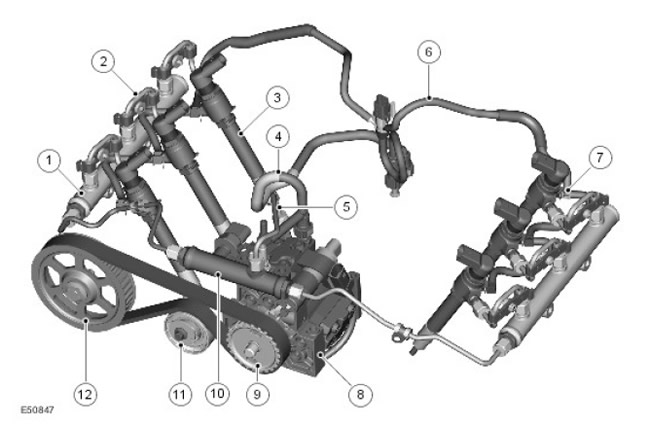
| Item name | Spare part number | Description |
| 1 | - | High pressure fuel rail (HP) (2 pcs.) |
| 2 | - | high pressure tube (HP) between fuel rail and injector (6 pcs.) |
| 3 | - | nozzles (6 pcs.) |
| 4 | - | Low pressure fuel pipe (LP): back drain |
| 5 | - | High pressure pipe between high pressure fuel pump and fuel rail |
| 6 | - | Low pressure fuel pipe: injector drain |
| 7 | - | Nozzle fitting (6 pcs.) |
| 8 | - | High pressure fuel pump |
| 9 | - | High pressure fuel pump pulley |
| 10 | - | High pressure distribution rail |
| 11 | - | Accessory drive belt tensioner from the rear end of the crankshaft (READ) |
| 12 | - | Left exhaust camshaft pulley |
General information
The TdV6 engine uses a battery injection system. In this system, the high pressure fuel pump (injection pump) supplies fuel at one pressure to two ramps, from which fuel enters all six nozzles. The pressure is maintained at an optimal level for trouble-free operation and can reach 1650 bar.
The battery system provides two-phase injection (preliminary and main phases), which reduces combustion noise and mechanical stress on engine parts.
The injection pressure is generated independently of the engine speed and fuel injection timing.
The engine control unit (ECM) calculates the time and volume of fuel injection and energizes the corresponding piezoelectric injector.
The battery injection system has the following features:
- Injection pressure can reach up to 1650 bar to obtain fine fuel crushing (fine atomization improves performance and reduces emissions of toxic combustion products)
- Independent regulation of injection parameters for cylinders ensures optimal combustion in all modes
- High accuracy throughout the life of the system
- Low pressure circuit (LP)
- High pressure circuit (HP)
- Fuel pump located in the fuel tank
- Fuel pressure regulator, built-in fuel delivery module
- Fuel filter
- Backflow pipes and fuel cooler
- Backflow pipes from injectors
- Fuel coolers (engine and car)
The high pressure circuit includes the following components:
- High pressure fuel pump
- Fuel rails and distribution rail
- High pressure fuel lines
- nozzles
Low pressure circuit
Fuel pump located in the fuel tank
An electric fuel pump is installed in the fuel tank. The fuel pump supplies fuel from the tank to the injection pump through the fuel filter. For more information refer to Fuel Tanks and Lines (310-01C Fuel Tank and Lines - 2.7L Diesel)
Fuel filter
The fuel filter is located on the left side of the engine compartment and is protected from mechanical damage. The fuel filter housing contains a bimetal bypass valve that starts to close at 30°C and closes completely at 50°C. This circulates heated diesel fuel inside the fuel filter and prevents wax formation in cold weather.
Fuel cooler
The fuel system is equipped with two fuel coolers. One is located in the collapse of the cylinder block and provides heat removal through connection with the cooling system. The second cooler is built into the return line and is air-cooled. For more information refer to Fuel Tanks and Lines (310-01C Fuel Tank and Lines - 2.7L Diesel)
High pressure circuit
High pressure fuel pump
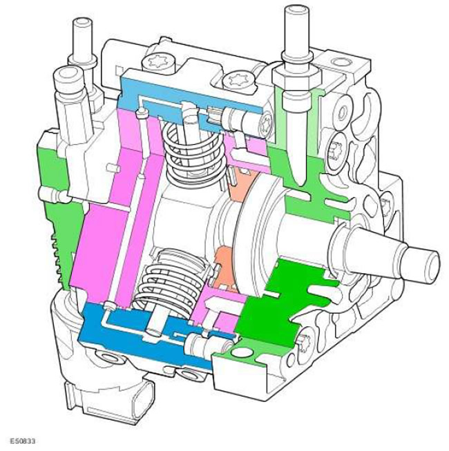
High pressure fuel pump, radial type, three-plunger (plungers are located through 120 degrees of a circle) with a working volume of 0.8 cubic meters. see As noted earlier, the pump can create pressures up to 1650 bar. The pump body is cast iron and the flange is aluminum.
The pump is driven by a toothed belt from the camshaft. After replacing the belt during maintenance, there is no need to synchronize the pump in terms of the angle of rotation of the crankshaft.
The supply pressure to the pump must be between -0.3 and +0.5 bar. Backflow pressure from -0.3 to +0.8 bar.
The pump has a capacity sufficient to provide the fuel rails with fuel in all engine operating modes. The high pressure pump contains the following components:
- Internal booster pump (ITP)
- Pump capacity regulator (VCV)
- Plungers (3 pcs.)
- pressure regulator (PCV)
The capacity controller is a solenoid spool valve that is controlled by the ECM. The VCV is located between the ITP and the plunger pairs. VCV regulates the amount of fuel supplied to the plunger pairs. If there is no signal to the VCV, the regulator valve closes and the fuel supply stops.
Three plunger pairs are connected by an annular fuel channel inside the pump housing. The injection pump has one outlet, to which a high-pressure pipe is connected, connecting the injection pump to the distribution rail.
pressure regulator (PCV) is a solenoid spool valve that is controlled by the ECM. The PCV is located between the plunger pairs and the injection pump outlet fitting. The pressure regulator controls the fuel pressure in the fuel rails and is controlled by the ECM. If there is no signal to the PCV, the regulator valve is open and the fuel rails are not pressurized.
The movement of fuel in the high pressure circuit
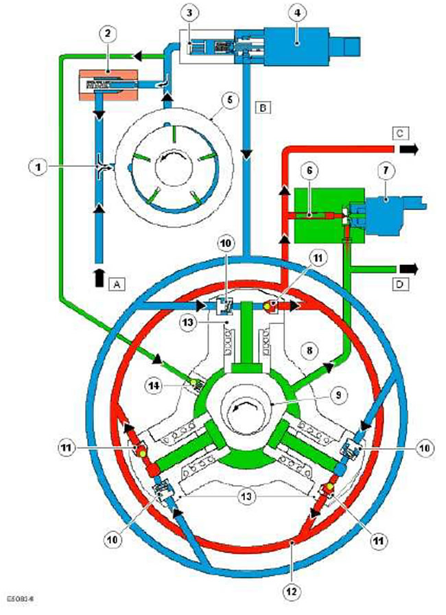
| Item name | Spare part number | Description |
| A | - | Fuel supply from the low pressure circuit |
| B | - | Fuel supply to plunger pairs |
| C | - | High pressure pipe to distribution rail |
| D | - | Backflow line (nozzle drainage) |
| 1 | - | Booster pump inlet |
| 2 | - | Booster pump pressure reducing valve |
| 3 | - | Strainer |
| 4 | - | Performance regulator (VCV) |
| 5 | - | Booster pump (ITP) |
| 6 | - | slot filter (to protect the pressure regulator valve) |
| 7 | - | pressure regulator (PCV) |
| 8 | - | - |
| 9 | - | Eccentric drive shaft injection pump |
| 10 | - | Plunger pair inlet valve |
| 11 | - | Plunger Pair Outlet Valve |
| 12 | - | High pressure annular channel |
| 13 | - | Plunger couples (3 pcs.) |
| 14 | - | Lubrication valve |
Fuel from booster pump (5) supplied to the performance controller (4) and to the lubrication valve (14). When the capacity control valve is closed, the boost pump pressure reducing valve (2), connected in parallel with this pump, opens and directs fuel back to the booster pump inlet (1).
Fuel flows through the lubrication valve (14) into the high pressure pump and from there to the return circuit (D). This fuel is used to lubricate the pump.
Performance regulator (4) determines the amount of fuel (IN), which is supplied to the plunger pairs (13).
Fuel from high pressure outlets (11) three plunger pairs are assembled together in the ring main (12) and is transmitted through the high pressure outlet to the ramps.
The fuel pressure in the rails is controlled by a pressure regulator (7). When the regulator reduces the pressure, the fuel returns to the low pressure circuit (D).
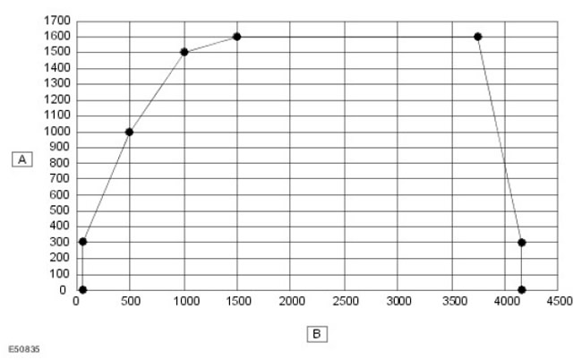
| Item name | Spare part number | Description |
| A | - | Pump pressure (bar) |
| B | - | Pump shaft speed (rpm) |
The injection pump can create fuel pressure up to 1600 bar in continuous mode and for a short time - up to 1650 bar. The pump shaft speed is 5/6 of the engine speed. However, the pump is configured in such a way that the fuel pressure depends on the engine speed and load and is continuously regulated.
Fuel pressure is generated by rotating the pump shaft when the VCV valve is open and the PCV valve is closed. The VCV and PCV valves can be set to different positions, which affects pump performance and fuel pressure.
When the engine control unit activates the piezoelectric injector actuator, the pressure drop in the rail is compensated by the pressure regulator.
Decrease in pressure after stopping the engine
After the engine stops, the pressure in the system decreases within a few seconds, as the pressure regulator is de-energized and its valve opens. There is no residual pressure in the system and the fuel is discharged into the return line (D) through an open PCV valve. The pressure in the system is not maintained.
Purpose of high pressure element A
Filling with fuel
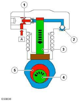
When the plunger (3) moves down, a vacuum is created above it, which, overcoming the resistance of the spring, opens the intake valve (1). Fuel (A), passing through the control valve is sucked into the plunger cylinder. Exhaust valve (2) at this time, it is closed due to the pressure difference in the plunger cylinder and the high pressure annular channel.
Fuel supply
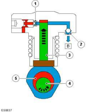
Eccentric (5) the drive shaft of the high pressure pump moves the plunger (3) up. Inlet valve (1) closes under the action of a spring, and the pressure in the pump cylinder begins to increase. Exhaust valve (2) opens when the pressure in the pump cylinder becomes higher than the pressure in the annular channel (IN) pump.
Pump capacity regulator (VCV)
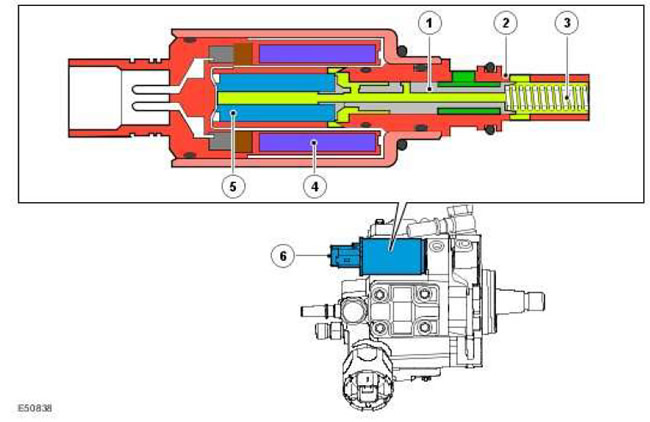
| Item name | Spare part number | Description |
| 1 | - | Piston |
| 2 | - | Sleeve |
| 3 | - | Compression spring |
| 4 | - | Winding |
| 5 | - | Core |
| 6 | - | Performance regulator (VCV) |
The performance regulator is installed directly on the injection pump.
The VCV valve regulates the amount of fuel supplied from the booster pump to the plunger pairs depending on the pressure in the fuel rail.
Thus, it is possible to bring the required performance of the injection pump into line with the flow of fuel at its inlet. At the same time, the amount of fuel going to the return drain is reduced to a minimum.
In addition, this reduces the load on the injection pump drive and, consequently, the specific fuel consumption.
NOTE: When power is turned off, the capacity control valve defaults to the closed position. Turning off the power to the regulator makes the engine work impossible.
NOTE: The capacity controller is not replaced as a separate assembly.
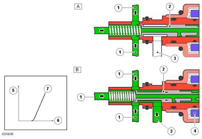
| Item name | Spare part number | Description |
| A | - | Performance controller off |
| B | - | Performance slider enabled |
| 1 | - | Fuel supply from booster pump |
| 2 | - | Piston |
| 3 | - | Fuel supply to injection pump |
| 4 | - | Winding power on |
| 5 | - | Fuel quantity |
| 6 | - | Control current strength |
| 7 | - | Regulator at constant crankshaft speed |
Performance controller off (A)
In the absence of power, the piston (2) under the action of the compression spring closes the hole between the channels (1) And (3). The fuel supply to the injection pump is shut off.
Performance slider enabled (B)
The motor control unit supplies power to the winding (4) valves according to the requirements of the engine. The pulling force of the winding, proportional to the strength of the control current, overcoming the force of the spring, moves the piston (2).
As a result, the piston opens two holes (1) And (3). Fuel quantity (5), supplied through the fitting (3) in high-pressure fuel pump, proportional to current strength (6). This means that the larger the flow area, the greater the pump performance.
Pressure regulator (PCV)

The pressure regulator is installed on the injection pump. It is designed to regulate the pressure at the outlet of the injection pump and, therefore, in the fuel rail. In addition, the pressure regulator dampens pressure fluctuations resulting from the operation of the injection pump and injectors.
The pressure regulator ensures optimal pressure in the ramps in all engine operating modes.
The pressure regulator is a solenoid valve with a spring-loaded spool.
When the engine control unit energizes the valve coil, the valve stem is pulled into the coil. In this case, diesel fuel passes by the locking ball and enters the ramps.
For cooling and lubrication, the core is immersed in fuel.
NOTE: The pressure regulator is not replaced as a separate unit.
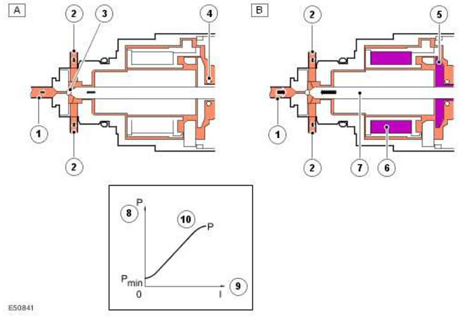
| Item name | Spare part number | Description |
| A | - | Pressure regulator not controlled |
| B | - | Pressure regulator controlled |
| 1 | - | Fuel from injection pump |
| 2 | - | To fuel return line |
| 3 | - | ball valve |
| 4 | - | Compression spring |
| 5 | - | Core |
| 6 | - | Winding power on |
| 7 | - | Stock |
| 8 | - | High pressure fuel |
| 9 | - | Control current strength |
| 10 | - | Characteristics of the pressure regulator |
Pressure regulator not controlled (A)
ball valve (3) is only under the action of the spring force (4). In this case, the pressure regulator is considered open.
Pressure regulator controlled (B)
Current flowing through the winding (6), displaces the stem (7) down. In this case, the magnetic force is transmitted through the stem to the ball valve (3). The balance of pressure on the ball on the stem side and on the fuel side determines the fuel flow through the valve (9).
High pressure fuel rails
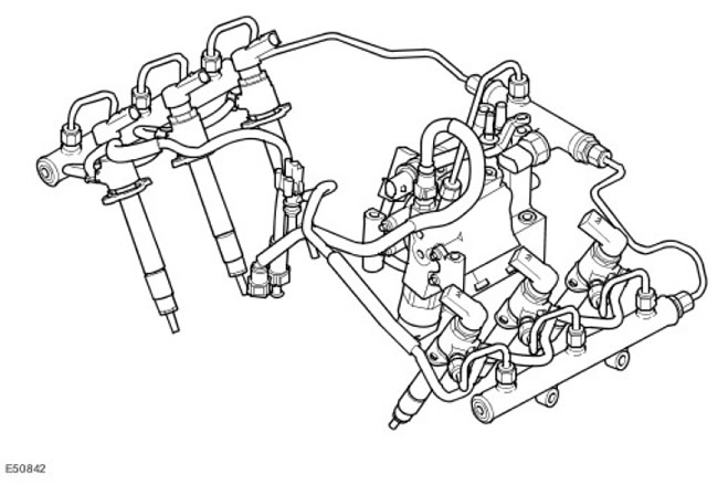
The high pressure fuel rails are made of forged steel. The fuel rails play the role of hydraulic fuel accumulators and, in addition, dampen pressure surges in the high pressure circuit.
The high pressure pipes have an internal diameter of 2.5 mm, except for the pipes for the injectors, which have a diameter of 3.0 mm. The total volume of the fuel rails is 33 cu. cm.
Nozzles
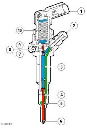
| Item name | Spare part number | Description |
| 1 | - | electrical connector |
| 2 | - | High pressure fuel supply |
| 3 | - | control piston |
| 4 | - | Atomizer needle |
| 5 | - | Nebulizer high pressure chamber |
| 6 | - | Atomizer holes |
| 7 | - | mushroom valve |
| 8 | - | Fuel drain |
| 9 | - | valve piston |
| 10 | - | Piezoelectric drive |
The fuel metering and timing of fuel delivery is controlled directly by the ECM.
A piezoelectric fuel injector consists of three main parts:
- Piezo drive
- Nozzle body with hydraulic booster system
- fuel injector nozzle
NOTE: New injectors DO NOT require calibration and can be installed in any cylinder.
NOTE: Each injection is controlled by a charge cycle, in which the electrical charge to the injector is increased, and a discharge cycle, in which the remaining electrical charge is dissipated. Never disconnect the electrical connector from the injector while the engine is running. The injector may remain open, causing engine damage.
NOTE: For safety reasons, the engine must be turned off for 30 seconds before working on the high pressure fuel system.
Fuel injector off (fuel is not injected)
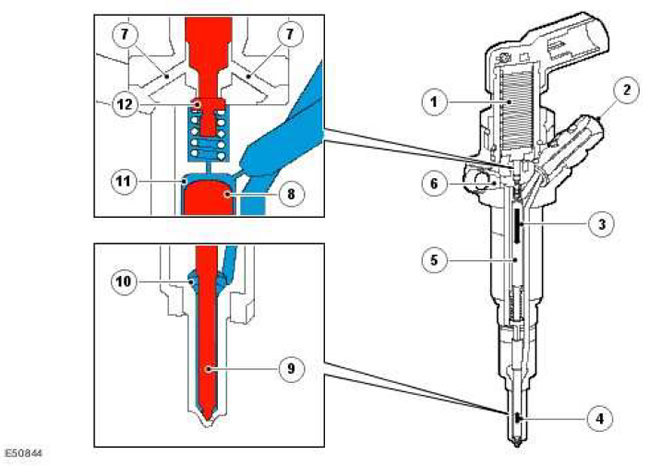
| Item name | Spare part number | Description |
| 1 | - | Piezoelectric drive |
| 2 | - | High pressure fuel supply |
| 3 | - | Pressure acting on the control piston |
| 4 | - | Pressure acting on the needle of the atomizer |
| 5 | - | control piston |
| 6 | - | Fuel drain |
| 7 | - | Fuel drain |
| 8 | - | control piston |
| 9 | - | Atomizer needle |
| 10 | - | high pressure chamber injector |
| 11 | - | control chamber |
| 12 | - | mushroom valve |
Fuel under high pressure passes from the rail through the fitting (2) to the control chamber (11) and into the pressure chamber (10) nozzle sprayer.
No current is supplied to the piezo drive (1), and mushroom valve (12) under the action of a spring closes the opening of the return drain channel (7).
Fuel resulting from internal leaks in the nozzle is discharged through the return channel (6).
hydraulic pressure (3), applied to the control piston (8) on the fuel side in the control chamber (11), more hydraulic pressure force (4) attached to the nozzle needle (the area of the control piston is greater than the area of the nozzle needle).
Fuel injector included (fuel injection)
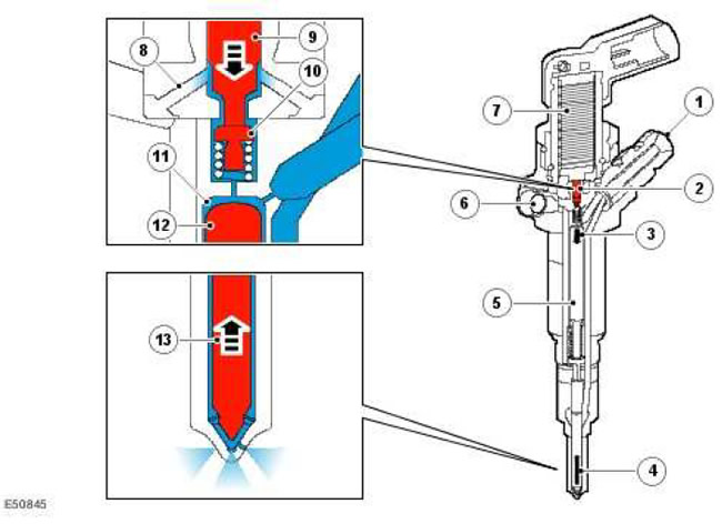
| Item name | Spare part number | Description |
| 1 | - | High pressure fuel supply |
| 2 | - | valve piston |
| 3 | - | Pressure acting on the control piston |
| 4 | - | Pressure acting on the needle of the atomizer |
| 5 | - | control piston |
| 6 | - | Fuel drain |
| 7 | - | Piezoelectric drive |
| 8 | - | Fuel drain |
| 9 | - | valve piston |
| 10 | - | mushroom valve |
| 11 | - | control chamber |
| 12 | - | control piston |
| 13 | - | Atomizer needle |
Piezo element (7) under the influence of an electric charge from the ECM expands (charge cycle) and presses on the piston (9) valve. mushroom valve (10) opens the hole that connects the control chamber (11) with backflow channels (8 and 6).
As a result, the pressure in the control chamber drops and the hydraulic force (4), acting on the atomizer needle becomes greater than the force (3), acting on the piston in the control chamber.
Atomizer needle (13) moves up and fuel is injected through the six holes of the atomizer into the combustion chamber.
Engine starting
To start the engine, a pressure in the fuel rails of at least 150 bar is required. If the pressure is below the specified value, the injectors will not work and, therefore, the engine will not start.
Engine stop
To stop the engine, the ECM cuts off power to the piezos. Fuel is not injected into the cylinders, and the engine speed drops to zero.
Comments on this article