Contents: Removal ⇩ Installation ⇩
Special tool
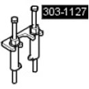 Fuel Injector Removal Tool 303-1127 Fuel Injector Removal Tool 303-1127 |
Removal
WARNING: Do not smoke or carry a lighted cigarette or open flame of any type when working on or near fuel-related components. There is a risk of ignition of flammable vapors. Failure to follow these instructions may result in personal injury.
CAUTION: Wait at least 30 seconds after stopping the engine before attempting any repairs to the high pressure fuel injection system. Failure to follow this instruction could result in personal injury.
CAUTION: This procedure involves handling fuel. Always be prepared for possible fuel splashing and follow safe fuel handling practices. Failure to follow these instructions could result in injury.
CAUTION: Do not carry out any repairs to the fuel injection system while the engine is running. Fuel pressure in the system can reach 1650 bar (23,931 psi). Failure to follow this instruction may result in injury.
CAUTION: Make sure that the area of the workshop where the vehicle is being worked on is thoroughly cleaned and free of dust. Dirt and dust from clutch, brake, machining or welding operations can contaminate the fuel system and result in improper operation.
CAUTION: Do not disconnect the fuel injector electrical connectors while the engine is running. Failure to do so may result in serious engine damage.
CAUTION: Always perform the cleaning procedure before performing any repairs to fuel injection system components. Failure to follow this instruction may result in dirt entering the fuel injection system.
CAUTION: Diesel fuel injection equipment is manufactured to very precise tolerances and with very small clearances. Therefore, it is especially important to maintain absolute cleanliness when working with these components. Open holes or lines should always be plugged using suitable plugs. Failure to follow this instruction may result in dirt entering the fuel injection system.
CAUTION: Do not disassemble the fuel injectors or clean their nozzles, even with ultrasound. Always install new fuel injectors when necessary.
1. Disconnect the ground cable from the battery. For more information, refer to Specification.
2. Remove the engine cover. For more information, refer to Engine Cover - 2.7L Diesel (12.30.50)
3. Disconnect the low-pressure fuel lines. Install plugs on the open connections.
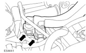
4. Disconnect both hoses from the EGR coolant bypass tube. Clamp the EGR coolant bypass tube to minimize coolant loss.
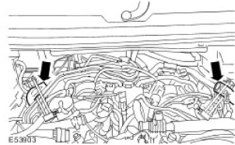
5. Remove the EGR coolant bypass pipe. Remove the 2 bolts.
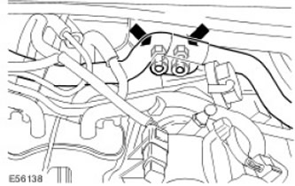
6. Remove the battery. For more information, refer to Battery (86.15.01)
7.
NOTE: A car with a right-hand steering wheel arrangement is shown, while a car with a left-hand steering wheel arrangement is performed in reverse order.
Disconnect the 3 engine wiring harness electrical connectors in the order shown.
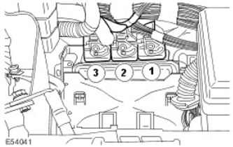
8. Release the engine wiring harness from the bulkhead.
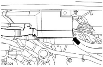
9. Remove the sound insulation from the fuel injectors.
10. Disconnect the fuel injector electrical connectors.
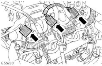
11. Release the engine wiring harness. Release the 4 clamps.

12.
CAUTION: Make sure that the high pressure fuel supply line remains in contact with the fuel injector and fuel rail until both nipple connections have been disconnected and cleaned. Failure to follow this instruction may result in dirt entering the fuel injection system.
CAUTION: Make sure that the fuel injector adapter nipple remains stationary when releasing the high-pressure fuel supply line. Failure to do so may result in failure of the fuel injector or the fuel injector adapter nipple.
Remove the high pressure fuel supply line and discard it.
- Loosen the high pressure fuel supply line fastener from the fuel injector and fuel rail.
- Install plugs on open connections.
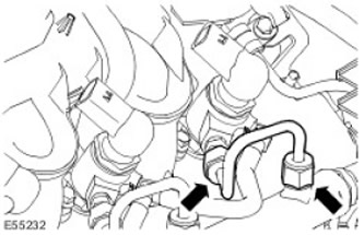
13. Disconnect the return fuel line from the fuel injector. Remove the return fuel line retaining clamp.
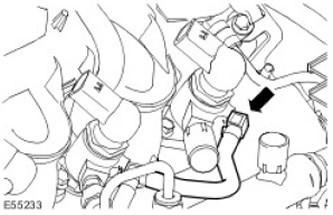
14. Unscrew the 2 fuel injector mounting bolts. Remove the fuel injector clamp spacer sleeve.
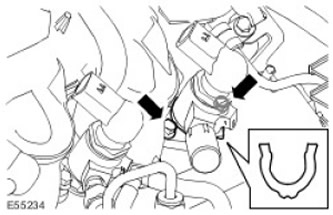
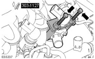
15. Install the special tool studs.
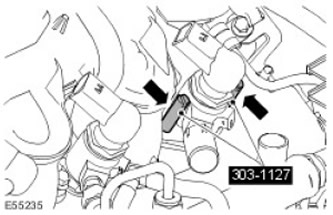
16.
CAUTION: Make sure the puller legs are properly engaged with the fuel injector. Failure to do so may result in damage to the component.
Place the legs of the special tool on the studs.
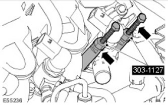
17. Remove the fuel injector.
- Install the special tool lock plate onto the special tool (puller) legs.
- Rotate the special tool bolts evenly clockwise.
- Remove the special tool.
- Remove and discard the fuel injector clamp.
- Remove and discard the sealing washer.
Installation
1.
CAUTION: Do not disassemble the fuel injectors or clean their nozzles, even with ultrasound. Always install new fuel injectors when necessary.
CAUTION: Do not use tools to install the new fuel return line retaining clip. Failure to do so may result in damage to the retaining clip.
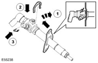
Install a new fuel injector clamp.
- 1. Install the fuel injector clamp spacer sleeve.
- 2. Install the new fuel return line retaining clip.
- 3. Install a new sealing washer.
2. Install the fuel injector. Insert and tighten the 2 bolts. (tightening torque 10 Nm).
3.
CAUTION: Make sure the fuel return line clamp is properly installed on the fuel injector before installing the fuel return line.
Connect the fuel return line to the fuel injector.
- Visually inspect the fuel return line O-rings for damage.
- Apply a thin layer of petroleum jelly to the fuel return line O-rings.
CAUTION: Avoid striking the sealing elements of the high-pressure fuel supply line, as this may damage the ends of the line and allow dirt to enter the fuel injection system.
CAUTION: When tightening the nipple connections, apply pressure to the high pressure fuel supply line to keep the sealing lenses in contact with the cones of the fuel injectors and fuel rail.
Install a new high pressure fuel line.
- Remove plugs from exposed connections.
- Step 1: Tighten the high pressure fuel line fitting on the injector side (tightening torque 15 Nm).
- Step 2: Tighten the high pressure fuel line fitting on the fuel rail side (tightening torque 15 Nm).
- Step 1: Tighten the high pressure fuel line fitting on the injector side (tightening torque 30 Nm).
- Step 2: Tighten the high pressure fuel line fitting on the fuel rail side (tightening torque 30 Nm).
6. Connect the fuel injector electrical connectors.
7. Install sound insulation for fuel injectors.
8. Connect the engine wiring harness to the bulkhead.
9. Connect the 3 electrical connectors of the wiring harness.
10. Install the battery. For more information, refer to Battery (86.15.01)
11. Install the EGR coolant bypass tube.
- Screw in the 2 remaining bolts.
- Tighten it up (tightening torque 13 Nm).
13. Connect the low pressure fuel lines. Remove the plugs from the exposed connections.
14. Install the engine cover. For more information, refer to Engine Cover - 2.7L Diesel (12.30.50)
15. Connect the ground cable to the battery. For more information, refer to Specification.
16. Check the coolant level and top up if necessary.
17. Remove air from the fuel system.
Comments on this article