


Contents: Removal ⇩ Installation ⇩
Special tool
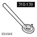 Retaining device 310-139 Retaining device 310-139 | 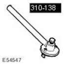 Puller 310-138 Puller 310-138 |
Removal
CAUTION: Never carry or use a cell phone while working with or in the immediate vicinity of any fuel-related component. Highly flammable mixtures are always present in such situations and may ignite. Failure to follow these instructions may result in injury.
CAUTION: Do not perform any repairs to the fuel system while the engine is running. Fuel pressure in the system can reach 1650 bar. Failure to follow this instruction may result in injury.
WARNING: Do not smoke or carry a lighted cigarette or open flame of any type when working on or near fuel-related components. Highly flammable mixtures are always present in such situations and may ignite. Failure to follow these instructions may result in injury.
CAUTION: This procedure involves handling fuel. Always be prepared for possible fuel splashing and follow safe fuel handling practices. Failure to follow these instructions could result in injury.
CAUTION: Make sure that the area of the workshop where the vehicle is being worked on is as clean and dust-free as possible. Dirt and dust from clutch, brake, machining or welding operations can contaminate the fuel system and cause malfunctions.
CAUTION: Always perform the cleaning procedure before performing any repairs to fuel injection system components. Failure to follow this instruction may result in dirt entering the fuel injection system.
CAUTION: Diesel fuel injection equipment is manufactured to very precise tolerances and with very small clearances. Therefore, it is especially important to maintain absolute cleanliness when working with these components. Open holes or lines should always be plugged using suitable plugs. Failure to follow this instruction may result in dirt entering the fuel injection system.
CAUTION: Do not disassemble the fuel pump or clean its interior, even with ultrasound. Always install a new fuel pump if necessary.
1. Disconnect the ground cable from the battery. For more information, refer to Specification.
2. Remove the engine crankcase ventilation oil separator.
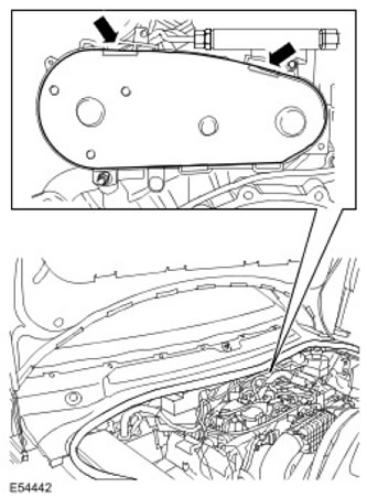
3. Remove the high pressure fuel pump drive belt cover.
- Move the engine wiring harness aside to gain access to the high pressure fuel pump drive belt cover.
- Release the two clamps.
4.
NOTE: The high pressure fuel pump drive belt is not linked to the engine valve timing.
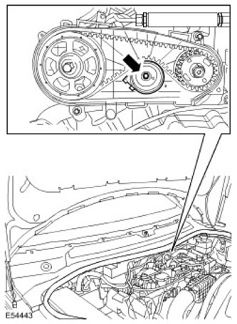
Remove the high pressure fuel pump drive belt tensioner and discard it. Unscrew the left mounting bolt.
5.
NOTE: The high pressure fuel pump rotates counterclockwise when viewed from the rear of the engine.
Remove the high pressure fuel pump drive belt and discard it.
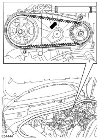
6. Remove the bolts securing the rear cover of the high-pressure fuel pump drive belt.
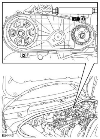
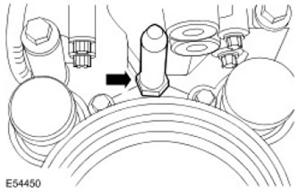
7. Remove the crankcase ventilation oil separator mounting stud.
8.
NOTE: Left side shown, right side is done in the same way.
Release the high pressure fuel supply lines. Remove the bolt.
9.
CAUTION: Make sure that the high pressure fuel supply line remains in contact with the fuel pump and intermediate fuel rail until both connections have been disconnected and cleaned. Failure to follow this instruction may result in dirt entering the fuel injection system.
NOTE: Left side shown, right side is done in the same way.
Remove and discard the high pressure fuel supply lines. Insert plugs into the open holes.
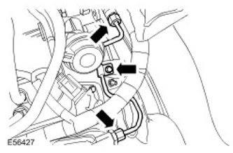
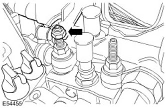
10. Release the fuel supply system wiring harness. Unscrew the nut.
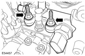
11. Remove the intermediate fuel manifold. Unscrew the two studs.
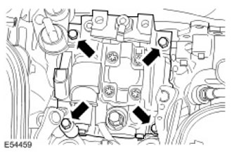
12. Remove the high pressure fuel pump. Unscrew the four bolts.
13.
NOTE: Do not continue disassembly if the component is removed only for access.
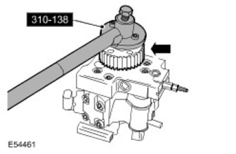
Using a special tool, unscrew the high pressure fuel pump pulley nut.
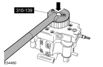
14. Using the special tool, remove the high pressure fuel pump pulley.
Installation
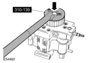
1. Using the special tool, install the high-pressure fuel pump pulley. Tighten to 50 Nm.
2. Install the high-pressure fuel pump. Tighten the bolts to 23 Nm.
3. Screw in the bolts securing the rear cover of the high-pressure fuel pump drive belt. Tighten to 7 Nm.
4.
CAUTION: Do not install the new fuel injection pump belt onto the pulleys with the tensioner installed. Failure to follow this instruction may result in damage to the fuel injection pump belt.
NOTE: The high pressure fuel pump rotates counterclockwise when viewed from the rear of the engine.
Install a new high pressure fuel pump belt.
5.
CAUTION: Make sure that the fuel injection pump drive belt tensioner tab is correctly positioned relative to the fuel injection pump drive belt rear cover. Failure to follow these instructions may result in engine damage.
Install a new high pressure fuel pump belt tensioner.
- Insert the tab on the new fuel injection pump belt tensioner into the fuel injection pump rear cover.
- Tighten to 25 Nm.
- Remove the high pressure fuel pump drive belt tensioner locking rod and discard it.
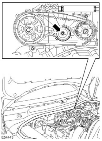
6. Install the fuel injection pump drive belt cover. Move the engine wiring harness to the side to gain access to the fuel injection pump drive belt cover.
7. Install the intermediate fuel manifold. Install the two mounting studs, but do not tighten them fully at this stage.
8. Secure the fuel supply system wiring harness. Screw on the nut.
9. Install new high pressure fuel supply lines.
- Open the holes covered with plugs.
- Install new high pressure fuel supply lines, but do not tighten them permanently.
- Tighten the intermediate fuel manifold mounting studs to 23 Nm.
- Step 1: Tighten the high pressure fuel supply line nipple connection on the fuel rail to 15 Nm.
- Step 2: Tighten the high pressure fuel supply line nipple connection on the intermediate fuel manifold to 15 Nm.
- Step 3: Tighten the high pressure fuel supply line nipple connection to the fuel rail to 30 Nm.
- Step 4: Tighten the high pressure fuel supply line nipple connection on the intermediate fuel manifold to 30 Nm.
- Screw in two bolts.
- Tighten to 10 Nm.
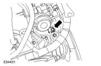
11. Screw in the crankcase ventilation oil separator mounting stud. Tighten the nut to 10 Nm.
12. Install the engine crankcase ventilation oil separator.
13. Connect the ground cable to the battery. For more information, refer to Specification.
14. Bleed the fuel system. For more information, refer to Bleeding the Low-Pressure Fuel System (19.50.07)
Comments on this article