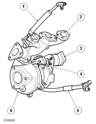
| Item name | Spare part number | Description |
| 1 | - | Oil supply pipe |
| 2 | - | Left exhaust manifold |
| 3 | - | Drive motor |
| 4 | - | drive lever |
| 5 | - | Oil drain pipe |
| 6 | - | Turbocharger |
In a variable nozzle turbocharger, depending on the operating conditions, the amount of exhaust gas passing through the turbine is controlled. The turbocharger is mounted on the left exhaust manifold of the TdV6 engine. This leads to an increase in the power available to the turbine and compressor, especially in the region of low crankshaft speeds, and to an increase in boost pressure. With an increase in engine speed, the blades of the apparatus gradually move to the open position, maintaining the balance of power realized on the wheel in accordance with the requirements of speed and load modes. Compared to traditional turbochargers that use bypass valves, the variable nozzle turbocharger provides higher efficiency. engine due to better use of the energy of the exhaust gases.
Advantages:
- High engine torque at high and low rpm
- Continuous optimal control at all engine speeds
- No boost pressure regulator required, better use of exhaust gas energy, less back pressure for the same compressor operation
- Low thermal and mechanical load increases the energy performance of the engine
- Reducing exhaust gas toxicity
- Optimization of specific fuel consumption in the entire speed range of the engine
The nozzle drive shaft is rotated by a DC motor. The drive shaft is connected to the blades by a drive lever. Moving the lever causes the blades of the apparatus to move. The rotation of the drive shaft generates a feedback signal that carries information about the angular position of the blades. This information is transmitted to the engine control unit (ECM).
The control box has a temperature sensor that takes the stepper motor to a safe position (completely open) when the maximum allowable temperature is exceeded. The engine control unit monitors the faults of the stepper motor and generates fault codes.
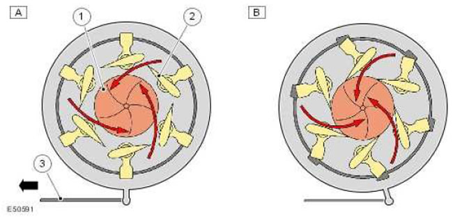
| Item name | Spare part number | Description |
| A | - | Closed (high speed) |
| B | - | open (low speed), default position |
| 1 | - | Turbine |
| 2 | - | Apparatus blades |
| 3 | drive lever |
At low engine speeds, the position of the vanes is such that the relatively slow exhaust gas flow is accelerated and enters the turbine wheel vanes at the greatest angle. Accordingly, a large torque is generated on the turbine wheel, and the wheel develops a high rotation speed.
At high engine speeds, the blades gradually open, and a large amount of exhaust gas reduces the speed and is directed towards the axis of the turbine wheel.
The torque on the turbine wheel is artificially reduced. In this way, the rotational speed of the turbine wheel, and hence the intake air flow, is controlled in accordance with the rotational speed of the engine crankshaft. The boost pressure remains approximately constant over the entire speed range of the engine.
Operating parameters are controlled by the ECM using transmission sensor data and driver commands. For more information refer to Electronic Engine Controls (303-14C Electronic Engine Controls - 2.7L Diesel)
The turbocharger provides fail-safe operation. In the event of a control failure, the machine's blades default to the fully open position to reduce the boost to a minimum.
Comments on this article