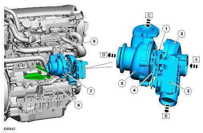
| Pos. | spare part no | Name |
| A | - | Air intake from the air filter |
| B | - | Compressed air to charge air cooler |
| C | - | Exhaust gas intake |
| D | - | Exhaust gas outlet |
| 1 | - | Oil supply line |
| 2 | - | Compressor housing |
| 3 | - | Rotating electronic actuator (REA) |
| 4 | - | Lever drive of the actuator for adjusting the position of the blades |
| 5 | - | Turbine casing |
| 6 | - | Turbocharger support bracket |
| 7 | - | Oil return line |
| 8 | - | An exhaust manifold |
The TD4 engine features a Garrett variable nozzle turbocharger with a rotating electronic actuator (REA). The turbocharger is mounted on the exhaust manifold on the right side of the engine and is attached to the cylinder block with a bracket. Oil pipeline with nipple connection type "banjo" is installed between the exhaust port on the right side of the cylinder block and the top of the turbocharger housing. It supplies pressurized oil to the turbocharger bearings. An oil line fixed at the bottom of the turbocharger is connected to the oil sump and directs the return oil from the turbocharger to the oil sump. A heat shield is installed above the turbocharger and exhaust manifold to protect other components and prevent accidental contact with hot exhaust system components.
The turbocharger includes a turbine and a compressor wheel mounted on a common shaft. They are enclosed in a cast housing. The common shaft is supported by two semi-floating bearings. The cast housing forms two chambers that tightly surround the compressor and turbine wheels. The turbine wheel is located in the flow of exhaust gases from the engine and exhaust system. The compressor wheel is located in the intake air stream between the air filter and the outlet to the aftercooler.
When the turbocharger is running, the turbine and compressor shaft can reach speeds of more than 200,000 rpm and provide charge air pressure (boost) up to 1.7 bar. Inside the turbine chamber, a pre-turbine pressure of 3 bar and a temperature of 800°C can be generated.
Attached to the compressor housing are REA elements, which are connected by a lever mechanism to a rotating adjusting ring located in the turbine housing. A set of radial adjustable blades is placed along the inner perimeter of the rotating adjusting ring. The adjustable vanes are positioned to interrupt the flow of exhaust gases from the engine, in front of the turbine wheel.
REA is controlled directly by the engine control module (ECM). The ECM constantly controls the position of the actuator using input from various sensors installed on the engine and vehicle. The feedback sensor in REA keeps the ECM informed of the position of the actuator when the turbocharger is running. When the adjustable vanes fail to reach the requested position, a DTC is stored in the ECM memory (DTC).
Comments on this article