car logo Ford
car logo Volkswagen
car logo BMW
car logo Opel
car logo Audi
car logo Toyota
car logo Peugeot
English Русский
Български
Беларускі
Український
Српски
Hrvatski
Română
Polski
Slovenský
Magyar


Main
Freelander
Discovery
Range Rover
Defender
Contacts
Articles

How a turbocharger works (Freelander 2)

 
  • Main
  • Freelander
  • Freelander 2
  • Power unit
  • Fuel supply
  • How a turbocharger works
 
        0  
The turbocharger uses the energy of the engine's exhaust gas flow to provide compressed air to the air intake system. Adjustable vanes allow the turbocharger to create the required boost pressure for the intake air for the current engine operating conditions.

A turbocharged engine provides the following advantages over a conventional direct-induction engine:
  • Higher volumetric efficiency.
  • Increased engine power and torque
  • Reduced fuel consumption
  • Reducing exhaust toxicity
  • Use of exhaust gas energy
  • No dependence on altitude above sea level
  • Limited periods of increased boost for immediate engine demand

A typical turbocharger driven by a rotating electronic actuator:
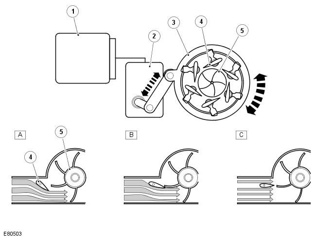
A typical turbocharger driven by a rotating electronic actuator:


Pos.Spare part numberName
A-Low engine crankshaft speed
B-Average engine crankshaft speed
C-Maximum engine speed
1-ECM
2-Rotary electronic actuator
3-Rotating adjustment ring
4-Adjustable paddles
5-Turbine wheel

In response to signals from various sensors, the ECM controls the REA to operate a rotating adjustment ring. Moving the adjustment ring changes the angle of the adjustable vanes to divert the exhaust gas flow toward the inner center or outer edge of the turbine wheel.


The maximum position of the variable turbocharger vanes (fully open position) is also the default emergency position in the event of an electrical problem. REA will move the variable vanes to the fully open position to prevent engine damage due to increased boost pressure.

A - low engine crankshaft speed


At low engine speeds, the volume of exhaust gases leaving the engine is low. The vanes move to the closed position to direct the flow of exhaust gases to the outer edge of the turbine wheel. The closed position of the vanes reduces the flow capacity of the gases and increases the velocity of the gases going to the turbine wheel. The speed of the turbine wheel increases, correspondingly increasing the amount of charge air (boost pressure) supplied by the compressor.

B - Average engine crankshaft speed


As the engine speed and exhaust gas volume increase, the vanes move to an open position to direct the exhaust gas flow toward the center of the turbine wheel. The vanes do not restrict the exhaust gas flow and therefore the velocity of the gases depends on the engine speed. The turbine wheel speed is maintained by increasing the velocity of the gases leaving the engine and directed toward the center of the turbine wheel.

C - Maximum engine speed


At maximum engine speed, the volume of exhaust gas leaving the engine is high. The vanes move toward the fully open position and do not affect the gas velocity. The exhaust gas flow contacts the central area of the turbine wheel to maintain the turbine wheel speed and the boost pressure from the compressor.


Increased boost pressure


During moderate to hard acceleration, the turbocharger must produce higher boost pressure for a limited period of time to meet the current fuel delivery needs of the engine. The ECM will request REA to move the variable vanes to the closed position to increase the speed of the turbine wheel, which is already spinning at high speed. The high boost pressure condition is tolerated by the ECM for a limited period.

Barometric pressure sensor


At high altitude, the turbocharger will operate normally, but due to the lower ambient pressure, the turbine and compressor may have a tendency to overspeed. The ECM contains a barometric pressure sensor to prevent excessive boost pressure and possible engine damage under these conditions. The ECM opens the variable vanes earlier in the opening phase to suit the vehicle altitude.

Turbocharger lubrication


Rapid acceleration and deceleration demands of the turbocharger depend on the stability of the flow of clean oil. The oil supplied by the engine lubrication system provides lubrication to the shaft and bearings of the turbocharger, while also acting as a coolant for the central housing of the turbocharger.

To maintain the expected service life of the turbocharger, the engine oil should be changed at regular service intervals using the recommended quality oil in the required quantity. The oil should have a free passage through the turbocharger and be able to return unrestricted to the oil sump.


This article is available at russian, bulgarian, belarusian, ukrainian, serbian, croatian, romanian, polish, slovak, hungarian
Article review: Roman Mitrofanov


Previous articles
Fuel system specification
Description of the fuel system
High pressure fuel pump
Common rail fuel manifold
Fuel injectors
High pressure fuel lines
Inspection and testing of the fuel system
Table of signs of malfunction

Current article
How a turbocharger works

Next articles
Turbocharger drive rod
Removal and installation a turbocharger


Similar articles from Land Rover repair manuals:
• How the Terrain Response system works Discovery 3 (2004-2009)
• Turbocharger outlet hose Discovery 1 (1989-1998)
• Turbocharger Range Rover 3 (2001-2012)
• Turbocharger Specifications Defender 2007+ (2007-2016)

Comments on this article


No comments yet


How much will 26 + 41 =


Freelander 2 
  • General information
  • Using the manual
  • Repair technique
  • Precautionary measures
  • Road test
  • Fault codes
  • Identification codes
  • Jacking and lifting
  • Maintenance - Diesel
  • Maintenance - petrol
  • Chassis
  • Suspension
  • Front suspension
  • Rear suspension
  • Wheels and tires
  • Terrain response
  • Transmission system
  • Cardan shaft
  • Rear drive axle
  • Rear axle shafts
  • Front axle shafts
  • Brake system
  • Parking brake
  • Hydraulic brake
  • Brake booster
  • Anti-lock braking system
  • Exchange rate stability
  • Steering
  • Steering column
  • Power unit
  • Engine device
  • Engine repair
  • Description of the cooling system
  • Cooling system repair
  • Fuel supply
  • Drive units
  • Launch system
  • Ignition system
  • Exhaust toxicity
  • Air filtration
  • Fuel vapor control
  • Electronic control part
  • Automatic gearbox
  • Gearbox cooling
  • Automatic transmission controls
  • Mechanical transmission
  • Transfer case
  • Exhaust system
  • Fuel tank and lines
  • Speed control
  • Electrical equipment
  • Climate control system
  • Climate control
  • Additional climate control
  • Instrument panel
  • Sound signal
  • Information and messages
  • Assistance with parking
  • Battery and alternator
  • Information and entertainment
  • Outdoor Lighting
  • Interior lighting
  • Communication network
  • Wiring harnesses
  • Anti-theft system
  • Multifunctional modules
  • Body and coating
  • Body front panels
  • Lockable body parts
  • Interior trim
  • Rear view mirrors
  • Car seats
  • Glass, frames and mechanisms
  • Instrument panel and console
  • Handles, locks, latches
  • Windshield wipers and washers
  • Sunroof
  • Bumpers
  • Seat belt system
  • Restraint system
  • Body repairs
  • Front end repairs
  • Roof element repairs
  • Side panel repairs
  • Tailgate repairs
  • Subframe and mounts

Freelander 1 
  • General information
  • Using the manual
  • Precautionary measures
  • Technique
  • Specifications
  • Connection tightening torques
  • Maintenance
  • Power unit
  • Diesel engine Td4
  • Petrol engine K1.8
  • Piston group K1.8
  • KV6 petrol engine
  • Piston group KV6
  • Decreased toxicity
  • Motor control EDC
  • Engine management MEMS
  • Motor control Siemens
  • Fuel supply diesel Td4
  • Fuel supply for K1.8 engine
  • Fuel supply of KV6 engine
  • Cooling diesel Td4
  • Engine cooling K1.8
  • Engine cooling KV6
  • Exhaust system Td4
  • Exhaust system K1.8
  • Exhaust system KV6
  • Clutch
  • Mechanical transmission
  • Transfer case
  • Automatic gearbox
  • Chassis
  • Drive shafts
  • Rear axle and final drive
  • Steering
  • Front suspension
  • Rear suspension
  • Brake system
  • Body and coating
  • Passive safety
  • Doors, locks and glass
  • Exterior body parts
  • Interior trim details
  • Seats
  • Roof hatch
  • Roof
  • Body geometry
  • Body parts repair
  • Sealing and corrosion
  • Electrical equipment
  • Heating and ventilation
  • Air conditioning
  • Windshield wipers and washers
  • Starting engine and charging
  • Lighting and headlights
  • Control modules
  • Safety system
  • Window management
  • Entertainment systems
  • Wiring harnesses
  • Governing bodies
  • Devices


LRman.ru © 2013-2026 | Mobile version | Free Lander | Discovery | Range Rover | Defender | Contacts | | Sitemap |
Car repair and service instructions Land Rover: Freelander, Discovery, Range Rover, Defender
We use cookies to make pages load faster and provide a more user-friendly experience 🍪