Contents: Dismantling ⇩ Assembly ⇩
The following procedure also applies to the removal/installation of the turbocharger gasket. Before disconnecting the battery, make sure that all requirements and conditions contained in the section on disconnecting the battery are met.
GENERAL INFORMATION, Precautions when working with electrical equipment.
Dismantling
1. Place the vehicle on a lift.
2. Disconnect the negative battery terminal.
3. Remove the exhaust pipe.
EXHAUST MANIFOLD AND EXHAUST SYSTEM: Td6 engine, REPAIR WORKS, Downpipe.
4. Remove the air cleaner filter element.
ENGINE MANAGEMENT SYSTEM Td6:, REPAIR WORK, Air cleaner filter element.
5. Remove the turbocharger air inlet hose.
ENGINE MANAGEMENT SYSTEM Td6:, REPAIR WORK, Turbocharger air intake duct.
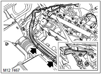
6. Disconnect the engine harness from the clamps and move it away from the valve cover.
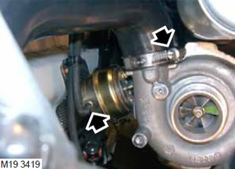
7. Loosen the clamp and disconnect the hose from the turbocharger that goes to the air-to-air cooler. Discard the clamp.
8. Disconnect the vacuum hose from the turbocharger bypass valve.
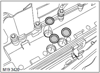
9. Remove the 3 bushings from the bottom of the air filter housing.
[The article is based on data from the website: www.LRman.ru]
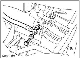
10. Remove the hollow bolt from the cylinder block that supplies oil to the turbocharger.
CAUTION: Before disconnecting or removing system components, make sure that the adjacent surfaces of the joints are free of dirt. Install plugs in the openings of the fittings and pipes to prevent dirt from entering the system.
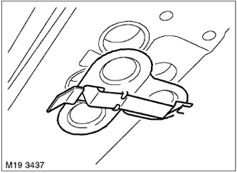
11. Remove the hatch cover from the heat shield.
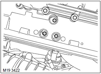
12. Unscrew the 3 bolts securing the turbocharger to the exhaust manifold.
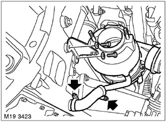
13. Loosen the 2 clamps and disconnect the oil drain hose from the cylinder block.
14. Unscrew the 2 bolts securing the turbocharger support bracket to the cylinder block and remove the turbocharger.
15. Remove and discard the turbocharger gasket.
NOTE: If disassembly was performed only to provide access to other system components, further disassembly operations should not be performed.
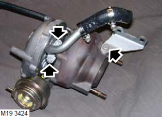
16. Loosen the support bracket mounting bolt and remove it.
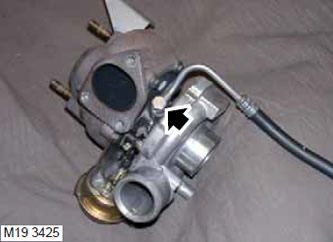
17. Note the position of the oil feed pipe, loosen the hollow bolt, remove the pipe and discard the sealing washers.
CAUTION: Before disconnecting or removing system components, make sure that the adjacent surfaces of the joints are free of dirt. Install plugs in the openings of the fittings and pipes to prevent dirt from entering the system.
Assembly
1. Wipe the turbocharger oil drain hose and mating surfaces.
2. Take a new gasket, install the oil drain hose and tighten the bolts. Tightening torque is 10 N·m.
3. Wipe the turbocharger oil feed pipe and mating surfaces.
4. Using new sealing washers, install the oil feed pipe, screw in the hollow bolt and tighten it. Tightening torque is 25 N·m.
5. Wipe the turbocharger and mating surfaces.
6. Install the turbocharger, screw the support bracket to the cylinder block without tightening them.
7. Install the turbocharger on a new gasket and tighten its mounting bolts. Tightening torque 50 Nm.
8. Tighten the turbocharger support bracket bolts. Tightening torque 25 N·m.
9. Install the oil drain hose and tighten the clamps.
10. Install the hatch cover onto the heat shield.
11. Install the bushings into the air filter housing.
12. Wipe the oil feed pipe and hollow bolt.
13. Using new sealing washers, install the oil feed pipe, screw in the hollow bolt and tighten it. Tightening torque 25 Nm.
14. Connect the vacuum hose to the turbocharger bypass valve.
15. Wipe the turbocharger pipe and the mating part of the air hose.
16. Install the turbocharger-to-intercooler hose. Use a new clamp. Tighten the clamp to 6 N·m (4.2 lb ft).
17. After waiting 15 minutes, tighten the clamp securing the air hose to the turbocharger again. Tightening torque 6 Nm.
18. Secure the engine harness to the clamps.
19. Install the turbocharger air inlet hose.
ENGINE MANAGEMENT SYSTEM Td6:, REPAIR WORK, Turbocharger air intake duct.
20. Install the air cleaner filter element.
ENGINE MANAGEMENT SYSTEM Td6:, REPAIR WORK, Air cleaner filter element.
21. Install the exhaust pipe.
EXHAUST MANIFOLD AND EXHAUST SYSTEM: Td6 engine, REPAIR WORKS, Downpipe.
22. Connect the negative battery terminal.
Comments on this article